
ABB AO2000-LS25 Laser Analysts User Manual
Alignment operation:
Remove the adapter ring of the transmitter/receiver and install the red laser calibration fixture.
Adjust the M16 adjustment screw on the transmitter side flange, align the laser beam with the center of the receiver side opening, and lock the locking screw.
Move the calibration fixture to the receiver side and repeat step 2 to align with the center of the opening on the transmitter side.
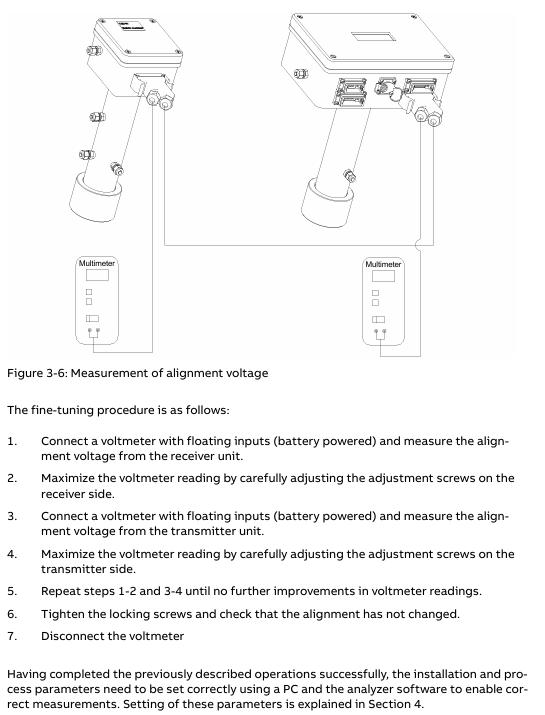
Connect the alignment interface of the transmitter/receiver with a voltmeter (voltage range 0V~-3V), fine tune the flange to maximize the voltage, and ensure that the transmission rate is between 90% -100% (low dust condition).
Software operation and parameter configuration
Software composition
Built in program: integrated into the CPU board, responsible for laser temperature control, signal acquisition, concentration calculation, and self checking, without the need for user operation.
Service program: Running on Windows system, connected to instruments via RS-232 or Ethernet, used for installation, configuration, calibration, troubleshooting, supporting user mode (simplified interface) and advanced mode (full functionality, password required).
Core function operation
Parameter configuration (via the "Measurement configuration" menu):
Temperature and pressure settings: Fixed value, 4-20mA input, internal sensor or spectral measurement (temperature only) can be selected, pressure unit is bar abs (gauge pressure needs to be converted: P (abs)=1.013+P (gauge)), temperature unit is ℃ (Fahrenheit conversion: T (℃)=(T (℉) -32)/1.8).
Optical Path: Set the "Optical Path Length (Gas)" (usually the diameter of the pipeline) and "Optical Path Length (Flange)" (only required when there is a target gas inside the flange). The factory preset "Optical Path Length (inside the transmitter/receiver)" cannot be modified arbitrarily.
Concentration averaging: Set the average number of times (N), and the average time Tavg=N × Tprim (Tprim is the single measurement time, 1-4 seconds, depending on the gas type).
Calibration operation (via the "Calibrate instrument" menu):
Calibration mode applicable scenario operation requirements
PROPORTIONAL's daily calibration and process gas calibration do not require temperature and pressure control, only adjusting calibration constants. It can calibrate a single gas separately and supports automatic calibration of associated gases
GLOBAL laser parameter drift, stable temperature and pressure environment (recommended 1.013bar, 23 ℃) after replacing core components, using standard gas and test cell, password authorization required
Recommended calibration gas concentrations: HF (50-500ppm, PTFE pool), HCl (15-200ppm), CO (0.5-5% vol or 50-500ppm), NO (500-5000ppm), etc.
Data log and fault viewing:
Log function: Set the sampling interval (minimum 2 seconds) through the "Log reads" menu, record parameters such as concentration, transmission rate, temperature and pressure, and support automatic generation of new files by date.
Fault viewing: The "View error log" menu displays fault/warning information (including activation/deactivation time), and can save fault logs and system logs for diagnosis. Common faults include "Low transmission" (cleaning window) and "Laser line up error" (realigning).
Maintenance and troubleshooting
routine maintenance
Regular inspection: Check the transmission rate daily, test the response with standard gas every 3 months (for at least 10 minutes), and calibrate every 3-12 months.
Window cleaning: When the transmission rate is too low, use non abrasive cleaning agents/solvents to clean the optical window. If the window has cracks, it needs to be replaced (pay attention to maintaining the original angle).
Blowing optimization: The flange blowing flow rate can be adjusted according to "blowing flow rate=1/10 process gas flow rate", and the blowing effect can be verified by observing the concentration change after turning off the blowing for 30-60 seconds.
Common faults and solutions
Analysis of the causes of fault information and solutions
Low transmission (warning) Optical window contamination, transmitter/receiver alignment deviation. Clean the optical window and re align the laser
Laser line up error: The laser beam did not reach the detector and the optical path was obstructed. Check for any obstacles in the optical path, clean the window, and realign it
PLC T-read error: Temperature sensor current exceeds the range (<0.3mA or>23.7mA). Check the sensor wiring or switch to a fixed temperature setting
Low laser temp. (Error) Laser temperature adjustment malfunction, laser supercooling check transmitter heat dissipation. If it is not overheated, it may be a hardware failure. Contact after-sales service
EEPROM error: Internal memory failure. Upload backup settings file. If it occurs repeatedly, contact after-sales service
Key issue
Question 1: What are the core differences between the two calibration modes (PROPORTIONAL and GLOBAL) of ABB AO2000-LS25 laser analyzer, and which scenarios are they applicable to?
Answer: The core differences between the two calibration modes are reflected in the calibration objects, operational requirements, and applicable scenarios:
- OMRON
- ABB
- General Electric
- EMERSON
- Honeywell
- HIMA
- ALSTOM
- Rolls-Royce
- MOTOROLA
- Rockwell
- Siemens
- Woodward
- YOKOGAWA
- FOXBORO
- KOLLMORGEN
- MOOG
- KB
- YAMAHA
- BENDER
- TEKTRONIX
- Westinghouse
- AMAT
- AB
- XYCOM
- Yaskawa
- B&R
- Schneider
- KONGSBERG
- NI
- WATLOW
- ProSoft
- SEW
- ADVANCED
- Reliance
- TRICONEX
- METSO
- MAN
- Advantest
- STUDER
- DANAHER MOTION
- Bently
- Galil
- EATON
- MOLEX
- DEIF
- B&W
- ZYGO
- Aerotech
- DANFOSS
- Beijer
- Moxa
- Rexroth
- Johnson
- WAGO
- TOSHIBA
- BMCM
- SMC
- HITACHI
- HIRSCHMANN
- Application field
- XP POWER
- CTI
- TRICON
- STOBER
- Thinklogical
- Horner Automation
- Meggitt
- Fanuc
- Baldor
- SHINKAWA
- Other Brands
- UniOP
- KUKA
- Iba
- Beckhoff
- ADLINK
-
 ETEL DSB2S154-211E-000H Servo Amplifier
 -
 ETEL DSCQT112-111-000 Motion Control Module
 -
 ETEL LMG20-050-3QB-211A Servo Motor – High Torque Linear
 -
 ETEL EU-LCP-0-0-1000-01 Communication Card
 -
 ETEL DSA2P174ZA-033A Servo Amplifier Driver
 -
 ETEL EA-P2M-400-15/40A-0100-00 Servo Driver
 -
 ETEL DSC2P152-111-000 Servo Drive Amplifier
 -
 ETEL LMS15-050-3UA-209A Linear Motor
 -
ETEL DSC2P152-111D-000A Controller
-
 ETEL DSB2P131-111E-000B Digital Servo Amplifier Position Controller
 -
 ETEL DSO-PWR111C-000B Power Supply Module
 -
 ETEL DSCDP324-321F-000C Servo Driver
 -
 ETEL DSC2P152-111B-000D Controller
 -
 ETEL DSB2P142-111E-000H Circuit Board
 -
 ETEL LMG05-030-3QA-H01 Linear Motor
 -
 ETEL DSC2P152-111F-000A Controller
 -
 ETEL DSA2S211ZA Servo Drive
 -
 ETEL DSCDM332-112-000 Drive Module
 -
 ETEL DSCDP334-421-000 Digital Position Controller Servo Drive
 -
ETEL EA-P2M-400-15/40A-0100-00 AccurET Servo Drive
-
 ETEL TMA0140-050-3UB-202B Torque Motor
 -
 ETEL DSA1DL1D.PCB Servo Drive Board
 -
 ETEL DSA2DL 1A Servo Drive
 -
 ETEL DSMAX111B-000B Servo Drive
 -
ETEL DSO-PWS111C-000B Power Supply Module
-
 ETEL DSC2P142-111B-000D Servo Drive Amplifier
 -
 ETEL DSC2P132-111D-000A Servo Drive Amplifier
 -
ETEL DSC2P152-111B-000D Servo Drive Amplifier
-
ETEL DSB2P131-121E-000H Servo Drive Amplifier
-
 ETEL DSB2P142-111E-000H Servo Drive Amplifier
 -
ETEL DSO-PWR112C-000A Power Supply Module – High Power
-
ETEL DSO-PWR111C-000A Power Supply Module
-
ETEL DSB2P121-121E-000H Servo Drive Amplifier
-
 ETEL DSB2S134-111E-000H Digital Servo Amplifier
 -
 ETEL RTMA0140-070-AQN-21E Motor
 -
ETEL DSCDP132-111-000 Dual Controller Circuit Board – Motion Control
-
 ETEL LMS15-050-3UA-209Aft Linear Motor
 -
 ETEL DSCDP324-322G-000A Position Controller
 -
ETEL DSA2P174ZA-033A Servo Amplifier Driver
-
 ETEL DSA2P174ZA-017A Servo Amplifier Driver
 -
 ETEL LMD10-050-3QA-223A Linear Motor
 -
ETEL EU-LGP-0-0-1000-00 PCI Network Card
-
ETEL DSO-PWS111C-000B Power Supply Module
-
ETEL DSC2V174-111C-001A Servo Controller
-
 ETEL EA-P2M-600-15/40A-0000-01 AccurET Modular Position Controller
 -
 ETEL RTMA0140-070-AQN-21B DD Motor
 -
 ETEL DSC2P144-421-000 Servo Driver
 -
ETEL EA-P2M-400-15-40A-0100-00 Servo Drive
-
ETEL DSCDM341-111C-000B Board
-
 ETEL LMD10-050-3QA-223A Motor
 -
ETEL RTMA0140-070-AQN-21E DD Motor
-
 ETEL DSCDM342-111-000 Servo Variator
 -
ETEL DSC2P152-111E-000A Servo Amplifier
-
ETEL LMS15-050-3UA-209A Motor
-
ETEL RTMA0140-070-AQN-21C DD Motor – High Torque Direct Drive
-
 ETEL DSCDP334-421G-000A Servo Drive
 -
Etel DSB2S154-211E-000H Digital Servo Amplifier
-
 ETEL EA-P2M-400-15/40A-0100-00 AccurET Servo Drive
 -
 ETEL DSA2P-174ZA-017A Digital Servo Amplifier
 -
ETEL EA-P2M-400-15/40A-0100-00 Servo Drive
-
ETEL LMP07-100-3TAS-229 Linear Motor Primary Part
-
ETEL LMA11-120-3ZA-359A Linear Motor
-
 ETEL EA-S0M-400-40/80A-0000-00 Drive Power Supply
 -
Etel DSCDP334-421-000 Driver
-
ETEL DSCDM341-111C-000B DSCDM Drive Board
-
Etel DSA1 Digital Servo Amplifier
-
ETEL DSA2P174ZA-033A Servo Amplifier
-
ETEL DSCDM342-111-000 Servo Verifier
-
 ETEL LMS15-050-3UA-209A Linear Motor
 -
ETEL P2M-048-2.5/5A AccurET Position Controller – Modular
-
ETEL LMD10-050-3QA-223A Linear Motor – Compact Precision
-
 ETEL EA-P2M-400-05/10A-0000-01 Drive – Precision Motion
 -
ETEL LMP07-100-3TAS-229 Linear Motor Primary Part
-
 ETEL EU-LGP-0-0-0000-00 Motion Control Card – Precision Control
 -
 ETEL DSC2P152-111E-000A Servo Amplifier
 -
ETEL EA-P2M-400-15/40A-0100-01 Servo Drive
-
 ETEL EA-SOM-300-40/80A-0000-00 AccurET Power Supply Module
 -
ETEL LMG10-1050-3QA-H01 Linear Motor
-
 ETEL EA-SOM-300-40/80A-0000-00 AccurET Modular Power Supply
 -
ETEL EA-P2M-400-15/40A-0100-00 AccurET Servo Drive
-
 ETEL EA-P2M-400-15/40A-0100-01 Servo Driver
 -
Etel RTMA0140-070-AQN-21B High Speed Motor
-
ETEL DSC2P141-111-000 Linear Servo Amplifier
-
ETEL DSB2S134-211E-000H Digital Servo Amplifier
-
ETEL 3LM-23C Motion Controller
-
Etel DSO-SER211-000 Power Add-On Board
-
ETEL DSCDP334-421-000 Servo Drive
-
 CTI-Cryogenics 8116071G001 Enhanced On-Board 8F Cryopump
 -
ETEL LMD10-050-3QA-223A Linear Motor
-
Etel DSO-SER211-000 Servo Card Power Add-On
-
ETEL LMG05-050-3QA-213A Linear Motor
-
Etel DSO-SER211-000 Power Add-On Board
-
ETEL EU-LGP-0-0-0000-00 Motion Control Card
-
ETEL EA-P2M-400-15/40A-0100-00 AccurET Servo Drive
-
 ETEL DSA2P1540A Digital Servo Amplifier
 -
ETEL DSC2P131-111-000 Drive Board
-
ETEL DSC2P131-111D-000A Servo Drive
-
Etel SA-IL 03-208 Linear Motor Section 208mm
-
 ETEL EA-P2M-300-4/7.5A-0000-01 AccurET Position Controller
 -
ETEL DSO-SER211-000 Power Board
-
ETEL DSC2P131-111F-000A Servo Amplifier
-
ETEL DSA1P6242B Digital Servo Amplifier
-
ETEL DSC2P131-111B-000B Regulator
-
ETEL DSA2P1540A Digital Servo Amplifier
-
ETEL EA-P2M-048-2.5/5A-0100-01 Drive
-
ETEL SA-LE 03-208 Linear Motor
-
ETEL DSO-PWS111B-000C Power Supply Module
-
 ETEL DSA2S211ZA-018A Digital Servo Amplifier
 -
ETEL DSA2P1643A Digital Servo Amplifier
-
ETEL DSC2P141-111-000 Linear Servo Amplifier
-
ETEL DSO-PWR111C-000A Power Supply Module
-
ETEL DSCDP132-111E-000A Dual Position Controller
-
ETEL DSCDM332-111C-000C Overload Protection Controller
-
ETEL EA-S0M-300-40/80A-0000-00 AccurET Modular Power Supply
-
ETEL DSO-PWR112C-000B Power Supply Module
-
Etel DSCDM343-111C-000B Position Controller
-
ETEL DSO-PWR111C-000B Power Supply Module
-
ETEL LMP07-100-3TAS-229 Linear Motor Primary Part
-
 ETEL DSCDP324-322G-000A Servo Amplifier
 -
 ETEL DSDP324-322F-000C Dual Motor Driver
 -
ETEL DSCDM341-111-000 PCB Board
-
ETEL SA-IL 03-208 Linear Motor
-
ETEL DSB2S234-111E-000H Digital Servo Amplifier
-
ETEL DSB2P131-111E-000B Digital Servo Amplifier
-
ETEL DSCDP121-111B-000A Speed Controller
-
ETEL DSCDM342-111-000 Servo Amplifier
-
ETEL IWM040-0256-00A Ironcore Linear Motor Magnetic Way
-
ETEL DSO-PWS111C-000B Power Supply Module


