
Yokogawa AQ6361 Optical Spectrum Analyzer
Yokogawa AQ6361 Optical Spectrum Analyzer
Functional positioning
The AQ6361 optical spectrum analyzer can achieve high-speed measurement of optical characteristics of devices such as laser diodes (LDs), light emitting diodes (LEDs), and optical amplifiers. The manual focuses on the "entry-level" operation of the equipment, covering handling precautions, installation steps, basic operations, and core specifications.
Open box verification and device model
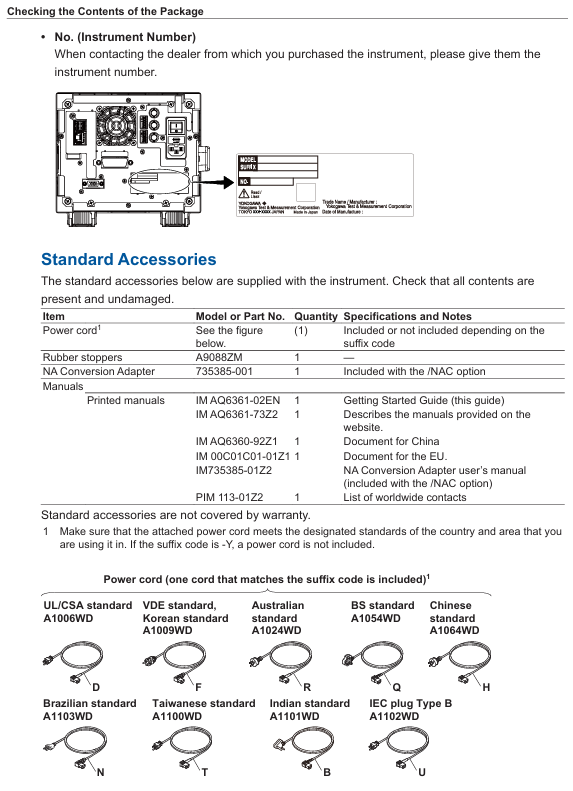
(1) Open box inspection content
After opening the box, the following items need to be checked. If there are any discrepancies in model, missing parts, or damaged appearance, please contact the Yokogawa distributor:
Host and identification: Confirm that the model and suffix on the back nameplate of the AQ6361 host are consistent with the order, and record the instrument number (to be provided when contacting the distributor).
Standard attachments:
|Item Name | Model/Part Number | Quantity | Description|
|Power cord | Determine based on suffix code (such as - D corresponding to UL/CSA standards) | 1 | Whether it is included depends on the suffix code and must comply with the standards of the region of use|
|Rubber pad | A9088ZM | 1 | Used to fix equipment and prevent sliding|
|NA Conversion Adapter | 735385-001 | 1 | Only available with/NAC option, matching manual is IM735385-01Z2|
|Printed manual | IM AQ6361-02EN, etc. | 1 each | Includes introductory guide, download instructions, region specific documents, etc|
|Global Contact Information Table | PIM 113-01Z2 | 1 | Yokogawa Global Office Contact Information|
Optional attachments (to be purchased separately):
|Attachment Name | Model | Specification|
|AQ9447 connector adapter | AQ9447-FC/AQ9447-SC | FC/SC interface, used for optical input|
|AQ9441 connector adapter | AQ9441-FC/AQ9441-SC | FC/SC interface, used for calibrating light source output|
|NA conversion adapter | 735385-001 | FC interface, suitable for GI 50/GI 62.5 fiber optic|
(2) Interpretation of Model and Suffix Codes
The model suffix code of AQ6361 determines the equipment specifications, and the core code meaning is as follows:
Category suffix code description
Performance Specifications -10 Standard Models -20 High Performance Models
Wavelength Range SW Standard Wavelength Range EW Extended Wavelength Range
Built in light source - L1 with wavelength reference light source - L0 without built-in light source
GP-IB interface - N01 without GP-IB interface - C01 with GP-IB interface
Power cord standard - D UL/CSA standard (125V) - F VDE/Korean standard (250V), etc
Optional accessories/FC with AQ9447 (FC) connector adapter/SC with AQ9447 (SC) connector adapter, etc
Safety regulations and installation requirements
(1) Core Security Warning
Electrical safety:
The equipment is an IEC Class I safety device and must be connected to a protective grounding. The power cord must use a grounded three core wire and the voltage must match the rated value of the equipment (90-264VAC, 50/60Hz);
Do not plug or unplug connectors when the power is turned on, and do not cut off internal/external grounding wires to avoid electric shock or equipment damage.
Laser safety (including L1 built-in light source model):
The equipment is an IEC 60825-1:2014 Class 1 laser product with a built-in reference light source (wavelength 1.53 μ m, output power 0.04mW). Infrared light is continuously emitted from the optical output connector, and direct viewing is strictly prohibited as it may cause visual impairment;
Avoid direct laser irradiation on the human body, especially the eyes, during measurement.
Environmental safety:
Prohibited from use in flammable and explosive environments, rainy or humid places;
The equipment is a Class A device used in industrial environments and may cause radio interference when used in residential areas. Users need to solve the interference problem themselves.
(2) Installation conditions
Physical environment:
The installation position should be horizontally stable to avoid vibration (vibration may cause a decrease in monochromator accuracy and measurement interruption);
There are ventilation holes on the side and back of the equipment, and the distance between the ventilation holes and surrounding objects should be kept at least 200mm to prevent internal overheating;
Environmental temperature: 5-35 ℃, humidity: 20% -80% RH (non condensing), avoid direct sunlight, near heat sources, and dust/corrosive gas environments.
Rack installation (requires separate purchase of rack kit):
|Kit Name | Model | Specification|
|EIA Single Installation Rack Kit | 751533-E4 | Suitable for EIA Standard Rack|
|JIS Single Installation Rack Kit | 751533-J4 | Suitable for JIS standard racks, etc|
During installation, it is necessary to remove the handles on both sides of the device and the bottom support feet to ensure that there is a reserved space of ≥ 10cm around the rack for heat dissipation, and the bottom support does not block the ventilation holes.
Equipment operation: from configuration to measurement
(1) Hardware connection and software configuration
Core hardware connection:
Optical interface connection: Optical input and calibration output need to be connected to optical fibers through corresponding connector adapters (such as AQ9447, AQ9441), and only FC/SC type optical connectors are supported;
- OMRON
- ABB
- General Electric
- EMERSON
- Honeywell
- HIMA
- ALSTOM
- Rolls-Royce
- MOTOROLA
- Rockwell
- Siemens
- Woodward
- YOKOGAWA
- FOXBORO
- KOLLMORGEN
- MOOG
- KB
- YAMAHA
- BENDER
- TEKTRONIX
- Westinghouse
- AMAT
- AB
- XYCOM
- Yaskawa
- B&R
- Schneider
- KONGSBERG
- NI
- WATLOW
- ProSoft
- SEW
- ADVANCED
- Reliance
- TRICONEX
- METSO
- MAN
- Advantest
- STUDER
- DANAHER MOTION
- Bently
- Galil
- EATON
- MOLEX
- DEIF
- B&W
- ZYGO
- Aerotech
- DANFOSS
- Beijer
- Moxa
- Rexroth
- Johnson
- WAGO
- TOSHIBA
- BMCM
- SMC
- HITACHI
- HIRSCHMANN
- Application field
- XP POWER
- CTI
- TRICON
- STOBER
- Thinklogical
- Horner Automation
- Meggitt
- Fanuc
- Baldor
- SHINKAWA
- Other Brands
- UniOP
- KUKA
- Iba
- Beckhoff
-
 Basler D90 96801 100 PCB Card
 -
 Basler XR2002F Voltage Regulator (110 VAC, 48-480 Hz)
 -
 Basler SR8A-2B14B3A Regulator
 -
 Basler 9561500100 Module
 -
 Basler DECS-400 BE1-11 System
 -
 Basler DECS-100-B15 Excitation Control
 -
 Basler SCP 210 Frequency Controller
 -
 Basler SR4A-2B15B3A Static Voltage Regulator
 -
 Basler BE1-32R Power Relay
 -
 Basler PIA2400-17GM Power Interface Adapter
 -
 Basler MVC 232 Manual Voltage Control Module
 -
 Basler SSR 32-12 Static Voltage Regulator
 -
 Basler 5MW AVR Generator Voltage Regulator
 -
 Basler VR63-4B Voltage Regulator
 -
 Basler DECS-100-A05 AVR for Engine Generator
 -
 Basler DECS-100-B15 Automatic Voltage Regulator
 -
 Basler BE1-32R Directional Power Relay
 -
 Basler BE1-87B Differential Relay
 -
 Basler UFOV 260A Protective Module
 -
 Basler 9-2614-02-100 PCB Rev M
 -
Basler DECS-100-B15 Digital AVR
-
 Basler 9284900103 PS DECS-400N
 -
 Basler D4N3H1U Intertie Protection
 -
 Basler DECS-100-B15 A15 AVR
 -
 Basler KR4F Voltage Regulator
 -
 Basler BE26434 T14 Transformer
 -
 Basler SR8A-2B15B3A Regulator
 -
 Westinghouse 774B472A12 AR Relay
 -
Basler DECS-100-B15 AVR
-
Basler XR2002F Regulator 110V
-
Basler SR125-E Static Regulator
-
 Basler SSR 125-12 Regulator
 -
 Basler MOC2599 Motor Pot
 -
 Basler BE1-DFPR Feeder Relay
 -
 Basler CBS 305 Current Boost
 -
 Basler BE1-25 AutoSync
 -
 Basler MVC 300 Voltage Control
 -
 Basler BE3-25A AutoSync
 -
 Basler KR7FF Static Regulator
 -
 Basler 90-49000-100 Regulator
 -
 Basler 880 kVA Dry Type Transformer Specs
 -
 Basler Electric BE1-25 Sync-Check Relay Specs
 -
 Basler SSR 125-12 Voltage Regulator Specs
 -
 Basler Electric BE1-851 Overcurrent Relay Review
 -
Basler Electric 149D930G02 Control Sub-Assembly
-
 Basler Electric BE1-81O/UT Frequency Relay Specs
 -
 Basler Electric BE1-51/27C Overcurrent Relay
 -
 Basler Electric 149D956G02 Industrial Component
 -
Basler Electric BE1-51A Overcurrent Relay Specs
-
 Basler Electric BE1-40Q Loss of Excitation Relay
 -
 Basler DECS-200 Excitation Control System
 -
 Basler DECS-200 Voltage Regulator 56-277V AC / 125V DC
 -
Basler BE1-87T Transformer Differential Relay
-
 Basler RDP-110-S1 Protection Relay
 -
 Basler BE1-700V Digital Protective Relay
 -
 Basler BE1-951 Overcurrent Protection System
 -
 Basler DECS-300 Digital Excitation Control
 -
 Basler DECS-200 Digital Excitation Control
 -
 Basler DECS-200-1C Excitation Control System
 -
Basler DECS-200-1L Digital Excitation Control
-
 Basler Electric BE1-GPS Generator Protection System
 -
Basler Electric DECS-200-1C Digital Excitation Controller
-
 Basler Electric DECS125-15 Excitation Control with Power Module
 -
 Basler Electric BE1-87G Differential Relay
 -
 Basler Electric BE1-11 Protection System I5A3M2P2N0EA00
 -
Basler Electric DECS-200-1C Excitation Control System
-
Basler Electric BE1-11g Generator Protection Relay
-
Basler Electric DECS 125-15-B2C1 V2.0.9 Excitation Control
-
 Basler Electric BE1-81O/UT3ED1JA7N2F Frequency Relay
 -
Basler Electric BE1-81O/UT3EE1YB7N1F Frequency Relay
-
 Basler Electric DECS-200-1L Digital Excitation Control System
 -
Basler DECS125-15-B2C1 Excitation Control
-
 Basler 9507900205 SSR Retrofit Voltage Regulator
 -
 Basler BE2000E Digital Voltage Regulator
 -
 Basler BE1-GPS Generator Protection System
 -
Basler DECS-250-CN1CN1N Digital Excitation Control
-
 Basler DGC-2020 Genset Controller
 -
 Basler BE1-81O UT3ED1LA7N0F Frequency Relay (Variant)
 -
 Basler BE1-81O UT3EE1YA9S0F Frequency Relay (Variant)
 -
Basler BE1-81O Over/Under Frequency Relay
-
Basler DECS125-15 Digital Excitation Control
-
Basler Electric BE1-951 Overcurrent Protection System
-
 Basler Electric BE1-700V Digital Protective Relay
 -
 Basler Electric APR63-5 Automatic Voltage Regulator
 -
Basler Electric BE1-851 Overcurrent Protection System
-
Basler Electric DECS-250-LN1SN1N Excitation Control
-
 Basler Electric BE1-87T Transformer Differential Relay
 -
Basler Electric DECS-200-1L Excitation Control System
-
 Basler Electric 9310300100 DECS-300 Excitation Control
 -
 Basler Electric SSE-N 125-4.5KW Shunt Exciter Regulator
 -
 Basler Electric DGC-2020HD-5NS1DNSBA Genset Controller
 -
Basler Electric BE1-81-O/UT3EE1JB7N1F Frequency Relay
-
Basler Electric BE1-81T1EE1WA0N1F Frequency Relay
-
 Basler Electric BE1-25M1EA6PN5R1F Sync-Check Relay
 -
 Basler Electric BE1-GPS Generator Protection System
 -
Basler Electric DECS-250-LN1SN1N Excitation Control Rev V
-
 Basler Electric DECS-250-CN2CN1N Excitation Control
 -
Basler Electric BE1-50/51B-207 Overcurrent Relay
-
Basler Electric DECS-300-C0N0 Excitation Control System
-
Basler Electric DECS-200 Digital Excitation Control System
-
Basler Electric DECS-250-LN1CN1N Excitation Unit
-
Basler Electric DECS-250 LN2SA1D Excitation Unit Specs
-
Basler Electric BE1-87T Transformer Relay Review
-
Basler Electric BE1-11 Protection System
-
Basler Electric BE1-GPS100-E4N1H1N Protection System
-
 Allen-Bradley 442G-MABH-R Safety Module
 -
 Beckhoff CX1030-0111 PLC Assembly Profile
 -
 FANUC IC693CPU364 PLC Module
 -
 Orange Denmark Type 200816 220 PLC Specs
 -
 OMRON C200H-SNT31 Sysmac PLC Module
 -
 Allen Bradley 20AB022A3AYNANC0 PowerFlex 70
 -
 OMRON C200HW-PCU01 Position Control Unit
 -
 ABB AO845A-eA Analog Output Module
 -
 OMRON CJ1M-CPU22 CPU Unit
 -
 Allen Bradley 100-E265ED11 Contactor
 -
 Honeywell 51304511-100 Interface Module
 -
 SOLEXY BXF3S0101N0018 Gateway Module
 -
 OMRON CJ2H-CPU65 CPU Unit
 -
 Automation Direct GS2-45P0 AC Drive
 -
 M68-2000 2-Axis Motion CNC Controller
 -
 OMRON CJ1M-CPU11 V3.0 PLC CPU Unit
 -
 OMRON CJ1W-NC413 4-Axis Positioning Controller
 -
 OMRON 3G2A3-PRO16 Programming Console HMI
 -
 Siemens 3VT8440-2AA04-2GA2 Molded Case Circuit Breaker
 -
 Siemens 3RT5045 Contactor Series
 -
 OMRON C200HS-CPU01-E SYSMAC PLC Controller
 -
 OMRON C500-NC103-E Positioning Control Unit
 -
 OMRON CJ1W-TC001 Temperature Control Unit


