
Yokogawa AQ6361 Optical Spectrum Analyzer
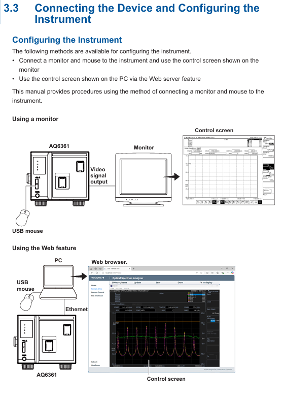
External device connection: PC connects devices through Ethernet/USB, monitor connects devices through Video OUT (XGA), mouse/keyboard connects through USB interface (supports USB HID Class 1.1 standard devices).
Software device registration and connection:
|Step | Operation Content|
|1 | Start AQ6361, enter the device connection window, click "Add" for the first connection, and select the communication method (Ethernet/USB)|
|2 | Click "Search" to search for devices, check the measuring instrument (such as AQ6361) and external devices, and click "Register" to complete the registration|
|3 | Check the target device in the registration list and click "Next" to enter the measurement and display settings window|
Key parameter configuration:
RAM data channel settings: Import symbol definition files (. a2l format) in the "Measurement Setting" window, or manually enter symbols, addresses, and data types to add RAM data channels;
Time reference synchronization: Check "Relative time" in "DAQ Setting", synchronize external devices based on the measuring instrument clock, and configure the data saving path (default: C: Users Username Documents YOKOGAWA IS8000).
(2) Startup and calibration process
Startup steps:
|Step | Operation Content|
|1. Connect the power cord, turn on the "MAIN POWER" switch on the back, and the front POWER light will turn orange|
|After waiting for a few seconds, press the "POWER" switch on the front, the light turns green, the device starts and initializes (displaying STEP 1/9 to STEP 9/9)|
|After initialization, enter the measurement interface and preheat for 1 hour before performing wavelength calibration|
Wavelength calibration (key step to ensure measurement accuracy):
Built in light source calibration (- L1 model): Connect the optical input and calibration output with 9.5/125 μ m single-mode fiber, enter "SYSTEM>Wavelength Calibration>Built in Source", click "Execute", and the calibration takes about a few minutes;
External light source calibration: Supports laser type (such as DFB-LD) or gas chamber absorption line type external light sources. After connection, set the wavelength in "External Laser/External Gas Cell" and perform calibration;
Attention: If the wavelength error exceeds ± 5nm, it is necessary to contact the Yokogawa dealer for re adjustment, as it cannot be calibrated through the built-in light source.
Resolution calibration: Use a stable single-mode laser source (output power ≥ -20dBm, linewidth ≤ 5MHz), connect it, enter "SYSTEM>Res BW Calibration", click "Execute" to complete the calibration, and the device will automatically correct the equivalent noise bandwidth after calibration.
(3) Measurement Execution and Data Management
Measurement condition setting:
Select the device in the "Device Control" panel, configure parameters such as sampling rate, trigger mode, sensitivity, and ensure that the measurement cycle of external devices (such as optical amplifiers) matches the pulse frequency of the device;
Supports three modes: "Single Sweep", "Repeat Sweep", and "Auto Sweep". Auto mode can automatically optimize measurement conditions.
Measurement operation:
|Operation | Function Description|
|Monitor Start | Start measurement (only monitors, does not record data)|
|Record Start | Start Record (Synchronize measurement and recording when monitoring is not started)|
|Record Stop | Stop recording (measurement continues)|
|Monitor Stop | Stop measurement (when recording has not stopped, synchronously stop measurement and recording)|
Data saving and loading:
The data is automatically saved in. mf4 format (including waveform and RAM data), and the default path can be modified in "DAQ Setting";
When loading data, the software opens the. mf4 file or loads the. wdf (waveform) and. mdf (RAM data) files offline, and the software automatically aligns the timeline.
Maintenance and troubleshooting
(1) Daily maintenance
Cleaning requirements:
Equipment casing: Wipe with a clean dry cloth after power failure, and prohibit the use of volatile chemicals (to prevent fading and deformation);
Optical interface: Clean the end face of the optical connector with a cotton swab dipped in pure alcohol to ensure that there is no dust (dust may affect optical performance and even damage the monochromator).
Regular inspection:
|Check project | cycle | operation content|
|Wavelength accuracy check | Regular | Use a light source with known wavelength accuracy (such as a gas laser) to measure the spectrum and confirm that the center wavelength error of THRESH 3dB is within the specified range|
|Level accuracy inspection | Regular | Using a 1310nm/1550nm light source, compare the peak level measured by the equipment with the reading of the optical power meter, and ensure that the error meets the specifications|
|Firmware Update | On Demand | Download the latest firmware from Yokogawa's official website and update via USB or Ethernet (power off is prohibited during update to avoid device failure to start)|
- OMRON
- ABB
- General Electric
- EMERSON
- Honeywell
- HIMA
- ALSTOM
- Rolls-Royce
- MOTOROLA
- Rockwell
- Siemens
- Woodward
- YOKOGAWA
- FOXBORO
- KOLLMORGEN
- MOOG
- KB
- YAMAHA
- BENDER
- TEKTRONIX
- Westinghouse
- AMAT
- AB
- XYCOM
- Yaskawa
- B&R
- Schneider
- KONGSBERG
- NI
- WATLOW
- ProSoft
- SEW
- ADVANCED
- Reliance
- TRICONEX
- METSO
- MAN
- Advantest
- STUDER
- DANAHER MOTION
- Bently
- Galil
- EATON
- MOLEX
- DEIF
- B&W
- ZYGO
- Aerotech
- DANFOSS
- Beijer
- Moxa
- Rexroth
- Johnson
- WAGO
- TOSHIBA
- BMCM
- SMC
- HITACHI
- HIRSCHMANN
- Application field
- XP POWER
- CTI
- TRICON
- STOBER
- Thinklogical
- Horner Automation
- Meggitt
- Fanuc
- Baldor
- SHINKAWA
- Other Brands
- UniOP
- KUKA
- Iba
- Beckhoff
- ADLINK
-
 Sigmatek MDD111-1 DIAS Drive Axis Module
 -
 Sigmatek DKL042 05-024-042 Terminal Module
 -
 Sigmatek DM822 Control Module
 -
 Sigmatek CDM167 12-008-167-O Module
 -
 Sigmatek TAE151 Touch Display Unit
 -
 Sigmatek DCC041 SLIDES Module 05-700-041-D
 -
 Sigmatek AKM65M-ANC2GBB0 PM Servo Motor
 -
 Sigmatek ETT221 01-230-221 Operator Terminal
 -
 Sigmatek SLIDES DAM 124 Analog Module
 -
Sigmatek AKM31C-ANCNGBB0 Servo Motor
-
 Mannesmann Demag Sigmatek CP626 Central Unit
 -
 SIGMATEK 0332.554.03 Board 371071000154
 -
 SIGMATEK 12-250-021 Base Plate Back Panel CM5V020
 -
 SIGMATEK DM162 S-DIAS Digital Mix Module
 -
 DEMAG ERGOTECH 061 381 66 Sigmatek 9842.243.02 Circuit Board
 -
 SIGMATEK CP313-1 PLC Module
 -
Sigmatek ETV0551-2 VARAN Touch Terminal
-
 Sigmatek SDM 081 FS S-Dias Safety Module
 -
 DEMAG 05-250-023 Ergotech Motherboard with Sigmatek TMS012
 -
Sigmatek CM5V020 12-250-023-K Wiring Base
-
 Sigma Tek 5000B-37 Attitude Gyro Indicator
 -
 Sigmatek SDD120-2 DIAS Drive
 -
 Sigmatek CME221 Memory Module
 -
 Sigmatek DCP640 DIAS Central Unit
 -
 Sigmatek STO040 Safety Output Module
 -
Sigmatek CET281 Control Panel
-
 Sigmatek CIPC LX800 Demag NC5 CPU
 -
 Sigmatek DKL093 05-024-093 Terminal Module
 -
 Sigmatek AI088 20-009-088 Analog Input Module
 -
Sigmatek CAI888 Analog Input Module
-
SIGMATEK CCA021 12-025-021 Analog Output Module
-
SIGMATEK 1104.579.05 Control Module
-
SIGMATEK SDI100 Digital Input Module
-
 SIGMATEK C-IPC 256MB LX800 Compact Dias
 -
 SIGMATEK 9423.090.02 Control Module
 -
SIGMATEK C-IPC 256 Power Supply 148498
-
 SIGMATEK CAI025 Analog Input Module
 -
 SIGMATEK CTO166 Digital Output Module
 -
 SIGMATEK CP112 20-004-112 Processor Module
 -
SIGMATEK CAI887 12-009-887 Safety Module
-
 Sigma-Tek 4000B-31 Directional Gyro 1U262-002-42
 -
Sigmatek C-IPC 256MB LX800 IPC Controller
-
Sigmatek C-IPC 01-450-031 Industrial PC LX800
-
Sigmatek C-IPC 256 Industrial PC Controller
-
Sigmatek CCP-531 PLC Processor Module
-
Sigmatek CDI163 Digital Input Module
-
 Sigmatek ETV0501 VARAN Terminal 12-230-0501
 -
 Sigmatek CTMS020 C-DIAS Technology Module
 -
 Sigmatek CIV512 VARAN Switch Module
 -
 Sigmatek HU011 20-080-011 Interface Module
 -
SIGMATEK SLIDES DAM 124 Module
-
 SIGMATEK C-IPC 161 01-450-161L Industrial PC
 -
SIGMATEK C-IPC 128MB VIA 733MHz 01-450-024-K
-
 SIGMATEK 12-780-012 R8-IPC Geode LX800 Module
 -
SIGMATEK CAM124 Analog Module
-
 SIGMATEK S1 032-8AF61-R4 EZ Servo Motor
 -
 SIGMATEK CTO163 Digital Output Module
 -
 SIGMATEK CCP082 12-004-082 Processor Module
 -
 SIGMATEK CRCH081 C-DIAS Temperature Module
 -
 SIGMATEK PC322-K 01-310-322-K Industrial PC
 -
SIGMATEK SDD310-2 Servo Drive
-
 SIGMATEK AI084 Analog Input Module
 -
SIGMATEK CRCH081 12-752-081 Temperature Module
-
Sigma-Tek 5000L-4 Attitude Gyro 1U284-001-3
-
 SIGMATEK CM5V020 12-250-023-K Wiring Module
 -
Sigma-Tek 4000H-6 Directional Gyro IU262-035-7
-
 SIGMATEK Dias DCP160 05-004-160 Processor Module
 -
SIGMATEK 0147.395.02 Control Module
-
SIGMATEK A1084 Control Module
-
SIGMATEK DI200 20-006-2000 Digital Input Module
-
Sigmatek DNC115 Encoder Module
-
 Sigmatek DAM122 05-017-122 Analog Module
 -
Sigmatek 9802.289.01 Control Board TA71 Display
-
Sigmatek TO127 20-007-127 Digital Output Module
-
Sigmatek DNC031 05-011-031 Digital Module
-
Sigmatek VI022 20-003-022 Interface Module
-
Sigmatek CAI085 Analog Input Module
-
 Sigmatek CP111 S-DIAS CPU Module
 -
Sigmatek CTMS030 Krauss Maffei Module
-
 Sigmatek CAM123 Control Module
 -
 Sigmatek TAE732-P 01-240-732-P Touch Display Unit
 -
Sigmatek MDM021 Digital Mixed Module
-
Sigmatek DCP642 DIAS Central Unit
-
 Sigmatek CST022 12-014-022 C-DIAS Module
 -
 Sigmatek SRO021 20-893-021 Safety Relay Output
 -
 Krauss Maffei MC5 Control System Sigmatek
 -
 Sigmatek DC061 Module 18-24VDC 300mA
 -
 Herrmann EVT0855 Ultrasonic Welder Touch Panel
 -
Sigmatek CIV521 Control Module 1.4A 2W
-
Sigmatek DDI61 05-006-161 Digital Input Module
-
SIGMATEK ETT312-E Touch Terminal 01-230-312
-
Cessna S3326-1 Sigma Tek 5000B-67 Gyro 1U149-015-9
-
SIGMATEK PS101 Power Supply Module
-
SIGMATEK 0332.554.03 Control Module 371071000154
-
 SIGMATEK ETT312-E Touch Terminal 01-230-312
 -
SIGMATEK CDM163 Control Module
-
 SIGMATEK VSV046 16-023-046 Module
 -
SIGMATEK AM221 20-017-221 Analog Module
-
SIGMATEK CTS051 12-053-051 Control Module
-
SIGMATEK AM221 20-017-221 Analog Module
-
Sigmatek CSDI161 12-891-161 Safety Input Module
-
Sigma Tek 4000C-1 Directional Gyro Indicator
-
Sigmatek ETV0501 12-230-0501 VARAN Terminal
-
Sigmatek DDM165 SLIDES Module
-
Sigmatek N100 20-011-100 Control Module
-
Sigmatek AKM54K-ANC2R-B0 PM Servo Motor
-
Sigmatek CTO166 Digital Output Module
-
Sigmatek CP212-K 20-004-212-K CPU Module
-
Sigmatek CDI161 Digital Input Module
-
Sigmatek DCC080 05-700-080-2 Control Module
-
 SIGMATEK SCP011 S-DIAS Safety CPU
 -
SIGMATEK SCP011 S-DIAS Safety CPU
-
SIGMATEK SRO022 Relay Output Module
-
SIGMATEK MDD 121 Drive Axis Module
-
SIGMATEK DSI021 SLIDES Siemens Interface
-
SIGMATEK DIAS DCP161 Module 05-004-161
-
 Sigmatek ETT312 Built-in Touch Terminal
 -
SIGMATEK DCP 643 DIAS Controller System
-
SIGMATEK CIO021 Multi I/O Module
-
SIGMATEK CTMS020 Control Module
-
 Sigmatek CME 221 Memory Module
 -
Sigmatek 0420.615.01 Control Board
-
Sigmatek CP111 20-004-111 CPU Module
-
Sigmatek 9405.065.03 Control Board
-
Sigmatek ETEK 01-450-032-K C-IPC 256MB Industrial PC
-
Sigmatek CTO163 12-007-163 Safety Output Module
-
Sigmatek TO081 20-007-081 Digital Output Module
-
 Sigmatek SI021 20-022-021 Safety Input Module


