How to maintain YOKOGAWA AQ7420 High Resolution Reflectometer?
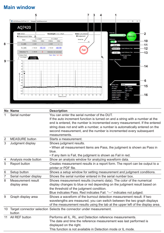
Waveform interaction: Drag and drop the mouse to pan the waveform, right-click or scroll to zoom in and out of a specific area, and use "DEFILT SCALE" to restore the default display scale.
Marking operation:
Click the "Marker Add" button to add markers on the waveform, and check the distance (mm) and RL value (dB) of the marker position.
Support calculating the distance difference and RL difference between two markers (such as A-B distance difference and RL difference) to assist in locating defect spacing.
Peak recognition: Reflection peaks that exceed the classification threshold are automatically marked, and the table displays the peak position, RL value, and classification result, making it easy to quickly locate outliers.
5. Data storage and printing
(1) Data saving
Manual Save: Click "SAVE" in the analysis window, and save the waveform data (CSV/JPG/BMP) according to the set path. The file name should include the date, time, and serial number (such as "PW20241115_103040-AA1. csv").
Auto Save: After enabling "Waveform Save", the measurement is automatically saved upon completion (only data classified as Fail is saved in NG mode to save storage space).
(2) Report printing
Click the "Report" button on the main interface to open the Windows print settings window, select the printer or "PDF" (generate PDF file).
The printed content includes instrument model, measurement time, set parameters, IL/RL/Detection results, waveform diagrams, and peak data, which are automatically summarized into a single page report for easy testing and archiving.

Remote control
1. Preparation for remote control
Hardware connection: The control PC is connected to the remote server via LAN, and the instrument is connected to the control PC via USB, ensuring that the network port (default 8889) is not blocked by a firewall.
Software settings: Enable "Remote Setting" in the PC application "Setup window → Remote Conditions", set the port number (consistent with the remote terminal), and enable "Local Key Display" to display the "Local Release Button" when connecting remotely.
2. Login and permission management
Login command: Remote terminal sends LOGIN<wsp>ID, Password. The default administrator ID/password is "reflectometer/reflectometer". After successful login, control the PC to display the "Remote" icon.
Permission classification:
Administrator: Can modify ID/password (IDWrite: ADMin<wsp>new ID, new password), create users (up to 5).
User: Only performs basic operations such as measurement and query results, and does not have permission to modify system settings.
Logout command: Send: LOGOut to disconnect the remote connection, or click on the control PC "Local Key" to force a switch to local control.
3. Core control commands
Remote control is based on TCP/IP protocol, with commands divided into "program messages" (control) and "query messages" (read). Examples of key commands are as follows:
Command group command example function
MAIN group: MAIN: EASure start/stop measurement
: MAIN: REF: ILREf Perform IL reference measurement
:MAIN:RESUlt:JUDGe? Query the overall judgment level result (0=Fail, 1=Pass)
SETUp group: SETUp: MODE<wsp>0 Set the operation mode to "IL, RL, Detection"
SETUP: EASure: STARt<wsp>20 Set measurement starting position 20mm
General command * IDN? Query instrument information (manufacturer, model, serial number, firmware version)
*RST resets instrument settings and stops all processes
The command supports abbreviations (such as SETUp, which can be abbreviated as SETU), is not case sensitive, the response message is in ASCII format, and the error command returns "Invalid Command".
Precautions and Maintenance
1. Measurement accuracy guarantee
Environmental control: IL measurement should be conducted in a constant temperature environment (temperature fluctuation within ± 1 ℃) to avoid direct blowing of instruments and cables by air conditioning; The cable layout needs to be fixed to reduce position deviation caused by vibration.
Cable maintenance: The main cable and sensor head connector need to be cleaned regularly (using specialized fiber optic cleaning paper). Scratches on the end face can cause measurement errors and need to be replaced in a timely manner.
Wavelength influence: When measuring SM fiber (1.31 μ m zero dispersion) at a wavelength of 1.55 μ m, it is affected by dispersion, resulting in low long-range reflection values; DSF fiber (1.55 μ m zero dispersion) does not have this problem, but 1.31 μ m measurement is affected by dispersion.
2. Troubleshooting
Possible causes and solutions for error phenomena
Refer to the measurement prompt for "Under Range" connector end face dirt/scratches, poor adapter coupling, clean end face (refer to section 2.5 of the manual), check adapter installation, replace damaged cables
Excessive waveform noise, strong total reflected light from DUT, improper measurement range setting, terminal matching with DUT end to reduce noise, switch RL measurement range to "-50~-100dB"
- ABB
- General Electric
- EMERSON
- Honeywell
- HIMA
- ALSTOM
- Rolls-Royce
- MOTOROLA
- Rockwell
- Siemens
- Woodward
- YOKOGAWA
- FOXBORO
- KOLLMORGEN
- MOOG
- KB
- YAMAHA
- BENDER
- TEKTRONIX
- Westinghouse
- AMAT
- AB
- XYCOM
- Yaskawa
- B&R
- Schneider
- Kongsberg
- NI
- WATLOW
- ProSoft
- SEW
- ADVANCED
- Reliance
- TRICONEX
- METSO
- MAN
- Advantest
- STUDER
- KONGSBERG
- DANAHER MOTION
- Bently
- Galil
- EATON
- MOLEX
- DEIF
- B&W
- ZYGO
- Aerotech
- DANFOSS
- Beijer
- Moxa
- Rexroth
- Johnson
- WAGO
- TOSHIBA
- BMCM
- SMC
- HITACHI
- HIRSCHMANN
- Application field
- XP POWER
- CTI
- TRICON
- STOBER
- Thinklogical
- Horner Automation
- Meggitt
- Fanuc
- Baldor
- SHINKAWA
- Other Brands


