
GE AT868 AquaTrans ™ Ultrasonic water flowmeter
GE AT868 AquaTrans ™ Ultrasonic water flowmeter
Product Overview
Core functions
AT868 is an ultrasonic water flow meter (supporting 1 or 2 channels) that measures water flow velocity, volumetric flow rate, and mass flow rate based on the principle of time difference. It is suitable for flow monitoring of single-phase fluids such as clean water and sewage. It emits and receives signals through ultrasonic sensors, calculates fluid flow velocity, and converts it into flow data, supporting real-time display, data recording, and multiple output methods (analog, pulse/frequency).
Main features
Multi channel configuration: Standard 1 channel, optional 2 channels, improve accuracy by measuring average, difference, or sum through dual channels.
Flexible sensor types: Supports wet and clamp on sensors to meet different pipeline installation requirements.
Rich output and communication: equipped with 0/4-20mA analog output, pulse/frequency output (for total count), supports RS232/RS485 serial communication, compatible with PanaView ™ Software remote operation.
High adaptability: Suitable for pipe diameters ranging from 0.04 inches to 200 inches (1mm to 5m), with flow rates ranging from -40 to 40 feet per second (-12.2 to 12.2m/s), meeting the needs of industrial pipeline flow monitoring.
Installation and wiring
1. Installation points
Sensor location: It needs to be installed in a straight pipe section, with at least 10 times the upstream pipe diameter and at least 5 times the downstream pipe diameter without turbulence interference (such as valves, elbows); Prioritize installation on the side of the pipeline (to avoid gas accumulation at the top or slag accumulation at the bottom).
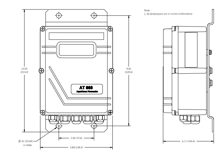
Electronic enclosure: Adopting NEMA 4X/IP66 protection level, suitable for indoor and outdoor installation, should be close to the sensor to shorten the cable length (supporting up to 1000 feet/300 meters).
Pipeline requirements: It is necessary to measure the outer diameter, wall thickness, material and other parameters of the pipeline and program them to ensure the accuracy of flow calculation.
2. Wiring specifications
Power supply: Supports 85-265VAC or 12-28VDC, requires an external power-off device (such as a switch) that complies with the EU Low Voltage Directive, installed within a range of 6 feet.
Sensor wiring: Plug in or clip on sensors are connected through coaxial cables, and the cable length needs to be matched (with an error of ≤ 4 inches for frequencies ≤ 2MHz and ≤ 0.5 inches for frequencies>2MHz).
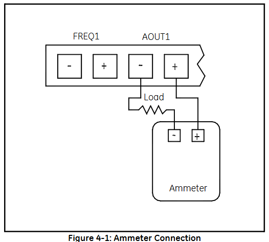
Output wiring:
Analog output (0/4-20mA): Load resistance ≤ 600 Ω, used for transmitting flow signals.
Pulse/frequency output: used for total count or frequency proportional to flow, maximum load 3A@100VDC .
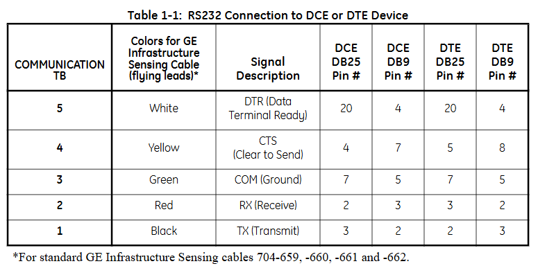
Communication wiring: RS232 is used to connect to PCs or printers, RS485 supports multi device networking, and must follow shielding grounding specifications to resist interference.
Programming and Settings
1. Basic parameter configuration
Channel activation: Activate the channel through the CHx ACTIV menu and select the sensor type (standard or special).
System parameters: Set the flow unit (such as gallon/minute, cubic meter/hour), total unit, and decimal places in CHx SYSTM, and optional mass flow rate (fluid density needs to be entered).
Pipeline and sensor parameters: Enter pipeline material, outer diameter, wall thickness, sensor frequency, path length (P), and axial length (L) in CHx PIPE. For clamp on sensors, lining parameters (material, thickness) also need to be set.
2. Advanced feature settings
Response time: Set the average measurement response time through the AVRG menu. It is recommended to select the "STATS" mode (fast response in steady state, fast tracking when flow changes).
Zero flow cutoff: Set a zero flow threshold (0-1 feet/second) in CHx I/O to avoid reading deviations caused by small fluctuations.
Tracking window: When the fluid sound velocity is unknown or fluctuates greatly, enable Tracing WINDOW to automatically track the sound velocity to ensure measurement accuracy.
Display function
1. Display screen and indicator lights
LCD display screen: A 2-line x 16 character LCD display screen that supports backlight adjustment and can display real-time measurement data, set parameters, and error codes.
Display content: It can be configured to display up to 4 parameters, including:
Flow rate (feet/second, meters/second)
Volume flow rate (such as gallons per minute, cubic meters per hour)
Accumulated total amount (such as total cubic feet, total cubic meters)
Diagnostic parameters (such as signal strength, sound speed, time difference, etc.)
Wheel display function: If multiple parameters are configured, the display screen will cycle at set intervals, with each parameter staying for a few seconds.
2. Display settings
Enter the settings menu:
Press [ESC]+[ENTER]+[ESC] to enter the user program.
Navigate to PROG → GLOBL → I/O → LCD, set the number of display parameters and specific parameters.
Parameter selection: Select the content to be displayed from the measured values (flow rate, flow rate) and diagnostic values (signal strength, sound velocity), supporting custom units (imperial/metric).
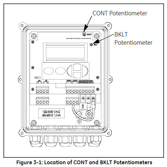
Contrast and brightness adjustment: Manually adjust through the potentiometer (CONT contrast, BKLT backlight) behind the panel to ensure clear visibility in different lighting environments.
Operation function
1. Totalizer Reset
Used to reset the accumulated traffic value to zero, supporting three methods:
Panel operation:
Enter the RESET menu and select YES to confirm the reset.
After resetting, the total amount of all channels will be reset to zero and accumulation will resume.
External switch reset:
Wiring should be done in advance (refer to the installation section) and configured as RESET in GLOBL-SYSTM → GATE OPTION.
Press and hold the external switch for 1 second, and the total amount will automatically reset to zero.
Software reset: via PanaView ™ The Clear Instrument Totalizers function of the software can be remotely operated.
2. Measurement pause and restart
Only supported through PanaView ™ Software operation:
Pause: Select Stop Measurement in Edit Functions → PAUSE MEASURMENT to pause the flow meter measurement and maintain the output signal at its final value.
Restart: Select Measure Flow to restore the measurement and update the output signal synchronously.
3. Diagnosis and Error Viewing
Diagnostic parameter display: Configure and display diagnostic parameters in GLOBL → I/O → LCD, including:
Upstream and downstream signal strength (SS up/SS dn, normal range 50-75)
Speed of Sound (SNDSP)
Time difference (DELTA T, normal ≤ 1 μ s)
Signal quality (Qup/Qdown, normal ≥ 1200)
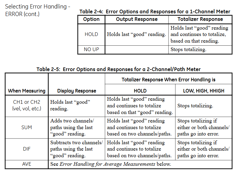
Error code: The display screen directly shows error codes (such as E1 indicating weak signal, E3 indicating flow rate exceeding limit). You can refer to Chapter 5 of the manual to investigate the cause (such as sensor alignment deviation, bubbles in the pipeline, etc.).
Key operation and menu navigation
1. Button functions
ESC: Exit the current menu or cancel the operation.
ENTER: Confirm the selection or enter the submenu.
↑/↓: Up and down navigation menu options or adjust parameter values.
←/→: Move the cursor (used to locate the digit when modifying parameters).
2. Common menu paths
View real-time data: default display interface, press ENTER to cycle through preset parameters.
Enter programming mode: ESC → ENTER → ESC → PROG, configurable channel parameters, units, outputs, etc.
Calibration output: ESC → ENTER → ESC → CALIB, used for calibrating 4-20mA analog output or pulse frequency output.
4、 Precautions
Display refresh rate: By default, it updates with the measurement cycle (response time can be set through the AVRG menu, ranging from 0.1-99 seconds).
Total overflow: When the cumulative value exceeds the maximum range, E9: Totalizer Overflow is displayed, and the total amount needs to be reset or the unit needs to be expanded (such as changing from "gallon" to "million gallon").
- OMRON
- ABB
- General Electric
- EMERSON
- Honeywell
- HIMA
- ALSTOM
- Rolls-Royce
- MOTOROLA
- Rockwell
- Siemens
- Woodward
- YOKOGAWA
- FOXBORO
- KOLLMORGEN
- MOOG
- KB
- YAMAHA
- BENDER
- TEKTRONIX
- Westinghouse
- AMAT
- AB
- XYCOM
- Yaskawa
- B&R
- Schneider
- KONGSBERG
- NI
- WATLOW
- ProSoft
- SEW
- ADVANCED
- Reliance
- TRICONEX
- METSO
- MAN
- Advantest
- STUDER
- DANAHER MOTION
- Bently
- Galil
- EATON
- MOLEX
- DEIF
- B&W
- ZYGO
- Aerotech
- DANFOSS
- Beijer
- Moxa
- Rexroth
- Johnson
- WAGO
- TOSHIBA
- BMCM
- SMC
- HITACHI
- HIRSCHMANN
- Application field
- XP POWER
- CTI
- TRICON
- STOBER
- Thinklogical
- Horner Automation
- Meggitt
- Fanuc
- Baldor
- SHINKAWA
- Other Brands
- UniOP
- KUKA
- Iba
- Beckhoff
-
 OMRON CJ1W-MD261 Mixed I/O Module
 -
 Omron NJ301-1100 PLC CPU eCat EIP Specs
 -
 Omron F500-C15-ETN Vision System PLC Module
 -
 Modicon M241-24IO TM/T2UK PLC with Ethernet
 -
 SIXNET YS-800-001 RTU PLC Module
 -
 BEMAC UST-202-D Interface Board 1307D V08B2
 -
 Yaskawa JANCD-MMOIC-02 Drive Circuit Board
 -
 ABB 3BSE005028R1 SDCS-COM-1 Comm Board
 -
 Omron 3G3MX2-A4110 A4150 Inverter Drives Specs
 -
 KEYENCE CA-E100 PLC Module
 -
 GE IC693ALG223-GB Analog Input Module Specs
 -
 ABB BAILEY IMMFP01 Multi Function Processor System
 -
 SIEMENS 6FC5372 0AA00 0AA1 NCU 7202 Controller
 -
Modicon TM241CE4 40I O Transistor Programmable Controller
-
 SIEMENS 6ES7 315 2EH13 0AB0 CPU 3152 PN DP
 -
 NORIS A1 91 PCB Card Rack Module System
 -
 SIEMENS 6ES7 313 5BE01 0AB0 Compact CPU
 -
 SCHNEIDER ELECTRIC S144B MICROLOGIC 60A Trip Unit
 -
 CNI PLC269 v3 Control Module Board Rev H
 -
ABB BAILEY IIMCP02 Processor Module
-
 OMRON NT20S ST121 EV3 Operator Interface Terminal
 -
 OMRON NS-CA001 Video Input Unit
 -
 GE Fanuc IC695CHS012 RX3i Backplane
 -
 Allen Bradley 2711E-K14C6 PanelView 1400e Terminal
 -
 Siemens Sinamics CCB 10000432.71 Power Cell
 -
 Siemens 6SL3210-1SE21-8UA0 Power Module PM340
 -
 Yaskawa CIMR-F7A20P4 AC Drive
 -
 Beckhoff EP1918-0002 EtherCAT Box I/O Module
 -
 OMRON CQM1-TC001 Temperature Control Module
 -
 GE Fanuc SGHA36AT0400 Industrial Contactor
 -
 OMRON NJ501-1500 PLC Machine Automation Controller
 -
 Mitsubishi MAZAK QX084 Power Supply MELDAS 500 CNC
 -
 B&R 0AC808.9 PLC Automation Module
 -
 OMRON CP1H-XA40DT1-D PLC Module
 -
 G&W Electric PLC15 5111 011 15kV Capnut Assembly
 -
 GE DS200SLCCG3AGH PCB Circuit Board
 -
 Siemens SINUMERIK 6FC3981-4FD PLC Extension
 -
 OMRON F300-DC I/O Image Processing Unit
 -
 FANUC A06B-0314-B002 AC Servo Motor
 -
 GC-S84 Programmable Controller Logic Module
 -
 PASABAN MONTELEC MTC3001-DC Drive Control PLC
 -
 Allen Bradley 100E460EJ11 Auxiliary Contactor
 -
 Bosch Rexroth 1070075337-101 Card Parameters
 -
 HMS Anybus AB7646-F Gateway Specifications
 -
 Bosch 062633-303401 CNC Servo PLC Card
 -
 TI 500-5023 Series PLC Power Supply
 -
 Siemens C98043-A7002-L1-12 Circuit Board
 -
 Omron E5CC-RX3A5M-000 Controller
 -
 CN-8032-L Profinet Network Adapter Module
 -
 Siemens 3TK2804-0BB4 Safety Relay Details
 -
 Toledo TTLM-2-1M I/O Load Module
 -
 NORIS A1-91 PLC Rack Board Specifications
 -
 Mitsubishi A3ACPUR21 MELSEC PLC CPU Module
 -
 Beckhoff EP7041‑3002 EtherCAT Box Digital Input Module
 -
 REER EOS2E 1053 EOS2R 1053 Safety Light Curtain
 -
 Mitsubishi Q80BD-J71BR11 MELSECNET/H Interface Board
 -
 Omron 3G3IV-B4220-EV2 VFD 400V 22kW
 -
 Allen-Bradley 96844671 1785-LT3 PLC-5/12 Processor Module
 -
 Pasaban MTC3001-DC Drive Control PLC Module
 -
 Omron CJ1M-CPU11 V4.0 PLC CPU Module
 -
 ABB CM579-PNIO B3 Communication Module
 -
 B&R X20 AI 4221 Analog Module
 -
 Siemens 6SY7000-0AC80 PLC Module
 -
 GE 531X300CCHAFM5 Control Card
 -
 AB 810-A15C Inverse Time Relay
 -
 WITTENSTEIN LP120X-MF2-20 Planetary Gear
 -
 Mitsubishi Kakoki E-01B-4130 PLC I/O Modules
 -
 ABB DSQC643 Safety Control Board
 -
 Siemens G26004-A2105-P100-2 PCB
 -
 OMRON F350-C10E Image Processing Unit
 -
 FUJI UG430H-TS1 HMI Touch Panel
 -
 Westronics CB100188-01 Rev F Board
 -
 Siemens 7MH4900-3AA01 Weighing Module
 -
 Gilbert & Nash Tracker 2000 Control Cabinet
 -
 OMRON CJ1M-CPU22 CPU Unit
 -
 OMRON F3SJ-E0625P25 Light Curtain
 -
 Siemens 3VA2340-5HL32-0AA0 Breaker
 -
 Mitsubishi Melsec A61P A2NCPU PLC System
 -
 Aeco 158-02 DSP-02 PCB Card
 -
 FUJI NP1PS-32R CPU Module
 -
 Siemens 6SL3040-1MA01-0AA0 Control Unit CU320-2 PN
 -
 Fuji RYE.75D PLC Driver AC Drive
 -
 Electro Cam PS-6144-24-P16M09-L-MB Programmable Limit Switch
 -
 Siemens C98043-A7001-L2-4 CUD1 Control Board
 -
 Pilz 312070 PSSu H PLC1 FS SN SD Safety Module
 -
 Siemens Plc42q4200atsn Circuit Breaker Fuse Box
 -
 GE Fanuc IC695ALG708-AB Analog Output Module Rx3i
 -
 Siemens 6SE7036-5GK84-1JC2 IGD8 Gate Driver Board
 -
 Charmilles 813078 852029 PLC PCB Robocut 2 CNC EDM
 -
 Siemens 6SL3130-1TE24-0AA0 Smart Line Module
 -
 Pasaban MTC3001-DC Drive Control PLC Module
 -
 Modicon AS-P890-000 Remote I/O Processor Power Supply
 -
 Siemens PXC100-PE96.A PXC Modular Controller
 -
 TOYO KEIKI P:CARD5 AVH-R YH-212 Industrial Control Card
 -
 Omron NS5-SQ00B-V2 HMI Touch Screen 5.7 Inch
 -
 Sciemetric SigPOD 1202-0H00 Data Acquisition Module
 -
 GE Fanuc IC693CPU331W CPU Module Series 90-30
 -
 Square D 8903SVO11V02 Lighting Contactor 200A
 -
 Beckhoff C9900-P224 Power Supply Unit 24V 10A
 -
 HSD PE323 PLC I/O Module
 -
 Pillar AB6406-11A Power Control Board
 -
 GE Fanuc IC693CPU331W CPU Module
 -
 FANUC A61L-0001-0072 LCD Monitor
 -
 AB 20D-D-011-A-0-EYNANANE Drive
 -
 AB 1785-L20B PLC-5/20 Processor
 -
 Siemens SIREC P/PA Recorder 7ND3021
 -
 Siemens D2E160-AH01-17 Fan Blower
 -
 Eaton 101073735-001 LEG Module
 -
 AB 1404-M605B-ENT Powermonitor 3000
 -
 OMRON CJ1W-MAD42 Analog I/O
 -
 Omron CJ1M-CPU13 V3.0 PLC CPU Module
 -
 Pe323 HSD PLC Module Industrial Controller
 -
 Pasaban MTC3001-DC Drive Control PLC Module
 -
 Mitsubishi R02CPU PLC Module MELSEC iQ-R
 -
 B&R X20DC2395 Digital Output Module 32 Ch
 -
 Hoffman A30N24ALP Enclosure with PLC Addons
 -
 Rieter PLC with RMC 24/5V 10 RMC188-1 RMC RIO-1
 -
 Allen-Bradley 1790D-TN4V0 CompactBlock LDX Base Block 4 AI
 -
 National Instruments NI 9242 Analog Input Module 4-Channel
 -
 ABB AO820 3BSE008546R1 Analog Output Module
 -
 Moeller XVC-101-C192K-K82 PLC
 -
 AB 440F-C4000P MatGuard Controller
 -
 AB 1692-ZRCLSS Protection Module
 -
 Schneider S48896 PLC Module
 -
 FANUC A02B-0303-C205 I/O Module
 -
 AB 1785-LT4 PLC-5/10 Processor
 -
 AB 1746-NO8V SLC 500 Analog Output
 -
 OMRON CQM1-TC001 Temperature Unit


