
GE AT868 AquaTrans ™ Ultrasonic water flowmeter
GE AT868 AquaTrans ™ Ultrasonic water flowmeter
Product Overview
Core functions
AT868 is an ultrasonic water flow meter (supporting 1 or 2 channels) that measures water flow velocity, volumetric flow rate, and mass flow rate based on the principle of time difference. It is suitable for flow monitoring of single-phase fluids such as clean water and sewage. It emits and receives signals through ultrasonic sensors, calculates fluid flow velocity, and converts it into flow data, supporting real-time display, data recording, and multiple output methods (analog, pulse/frequency).
Main features
Multi channel configuration: Standard 1 channel, optional 2 channels, improve accuracy by measuring average, difference, or sum through dual channels.
Flexible sensor types: Supports wet and clamp on sensors to meet different pipeline installation requirements.
Rich output and communication: equipped with 0/4-20mA analog output, pulse/frequency output (for total count), supports RS232/RS485 serial communication, compatible with PanaView ™ Software remote operation.
High adaptability: Suitable for pipe diameters ranging from 0.04 inches to 200 inches (1mm to 5m), with flow rates ranging from -40 to 40 feet per second (-12.2 to 12.2m/s), meeting the needs of industrial pipeline flow monitoring.
Installation and wiring
1. Installation points
Sensor location: It needs to be installed in a straight pipe section, with at least 10 times the upstream pipe diameter and at least 5 times the downstream pipe diameter without turbulence interference (such as valves, elbows); Prioritize installation on the side of the pipeline (to avoid gas accumulation at the top or slag accumulation at the bottom).
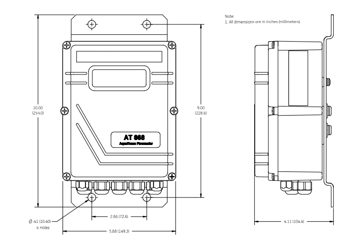
Electronic enclosure: Adopting NEMA 4X/IP66 protection level, suitable for indoor and outdoor installation, should be close to the sensor to shorten the cable length (supporting up to 1000 feet/300 meters).
Pipeline requirements: It is necessary to measure the outer diameter, wall thickness, material and other parameters of the pipeline and program them to ensure the accuracy of flow calculation.
2. Wiring specifications
Power supply: Supports 85-265VAC or 12-28VDC, requires an external power-off device (such as a switch) that complies with the EU Low Voltage Directive, installed within a range of 6 feet.
Sensor wiring: Plug in or clip on sensors are connected through coaxial cables, and the cable length needs to be matched (with an error of ≤ 4 inches for frequencies ≤ 2MHz and ≤ 0.5 inches for frequencies>2MHz).
Output wiring:
Analog output (0/4-20mA): Load resistance ≤ 600 Ω, used for transmitting flow signals.
Pulse/frequency output: used for total count or frequency proportional to flow, maximum load 3A@100VDC .
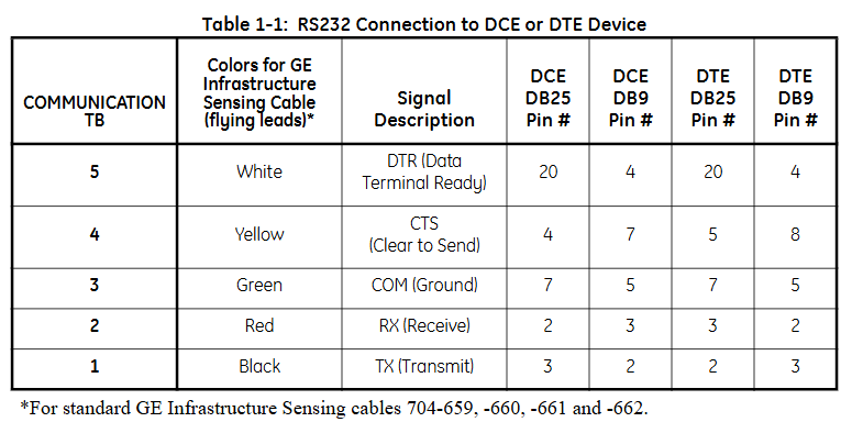
Communication wiring: RS232 is used to connect to PCs or printers, RS485 supports multi device networking, and must follow shielding grounding specifications to resist interference.
Programming and Settings
1. Basic parameter configuration
Channel activation: Activate the channel through the CHx ACTIV menu and select the sensor type (standard or special).
System parameters: Set the flow unit (such as gallon/minute, cubic meter/hour), total unit, and decimal places in CHx SYSTM, and optional mass flow rate (fluid density needs to be entered).
Pipeline and sensor parameters: Enter pipeline material, outer diameter, wall thickness, sensor frequency, path length (P), and axial length (L) in CHx PIPE. For clamp on sensors, lining parameters (material, thickness) also need to be set.
2. Advanced feature settings
Response time: Set the average measurement response time through the AVRG menu. It is recommended to select the "STATS" mode (fast response in steady state, fast tracking when flow changes).
Zero flow cutoff: Set a zero flow threshold (0-1 feet/second) in CHx I/O to avoid reading deviations caused by small fluctuations.
Tracking window: When the fluid sound velocity is unknown or fluctuates greatly, enable Tracing WINDOW to automatically track the sound velocity to ensure measurement accuracy.
Display function
1. Display screen and indicator lights
LCD display screen: A 2-line x 16 character LCD display screen that supports backlight adjustment and can display real-time measurement data, set parameters, and error codes.
Display content: It can be configured to display up to 4 parameters, including:
Flow rate (feet/second, meters/second)
Volume flow rate (such as gallons per minute, cubic meters per hour)
Accumulated total amount (such as total cubic feet, total cubic meters)
Diagnostic parameters (such as signal strength, sound speed, time difference, etc.)
Wheel display function: If multiple parameters are configured, the display screen will cycle at set intervals, with each parameter staying for a few seconds.
2. Display settings
Enter the settings menu:
Press [ESC]+[ENTER]+[ESC] to enter the user program.
Navigate to PROG → GLOBL → I/O → LCD, set the number of display parameters and specific parameters.
Parameter selection: Select the content to be displayed from the measured values (flow rate, flow rate) and diagnostic values (signal strength, sound velocity), supporting custom units (imperial/metric).
- OMRON
- ABB
- General Electric
- EMERSON
- Honeywell
- HIMA
- ALSTOM
- Rolls-Royce
- MOTOROLA
- Rockwell
- Siemens
- Woodward
- YOKOGAWA
- FOXBORO
- KOLLMORGEN
- MOOG
- KB
- YAMAHA
- BENDER
- TEKTRONIX
- Westinghouse
- AMAT
- AB
- XYCOM
- Yaskawa
- B&R
- Schneider
- KONGSBERG
- NI
- WATLOW
- ProSoft
- SEW
- ADVANCED
- Reliance
- TRICONEX
- METSO
- MAN
- Advantest
- STUDER
- DANAHER MOTION
- Bently
- Galil
- EATON
- MOLEX
- DEIF
- B&W
- ZYGO
- Aerotech
- DANFOSS
- Beijer
- Moxa
- Rexroth
- Johnson
- WAGO
- TOSHIBA
- BMCM
- SMC
- HITACHI
- HIRSCHMANN
- Application field
- XP POWER
- CTI
- TRICON
- STOBER
- Thinklogical
- Horner Automation
- Meggitt
- Fanuc
- Baldor
- SHINKAWA
- Other Brands
- UniOP
- KUKA
- Iba
- Beckhoff
- ADLINK
-
 Rolls-Royce R02TCN-E0L3-00 Remote Controller Features
 -
 Etel SA-IL 03-208 Linear Motor Section
 -
ETEL ILM03-060-3RA-A00 Ironless Linear Servo Motor
-
 ETEL DSCDP321-121-000 Dual Position Controller Board
 -
 Etel DSCDP121-111F-000A Dual Axis Servo Drive
 -
 Etel EA-S0M-400-40/80A-0000-00 AccurET Modular Power Supply
 -
 Etel TMB+0291-150-RO-00000-0A0 Rotor
 -
 ETEL DSCDP131-111F-000A Position Controller
 -
 ETEL DSC2P154-421F-000A Servo Drive
 -
 ETEL DSO-SER211-000 Add-On Power Board for Servo Amplifier
 -
 ETEL 613712-05 4-Axis Control Assembly
 -
 ETEL P2M-300-07/15A Accuret Position Controller
 -
 ETEL LMP07-100-3TAS-229 Motor Ruler Primary Part
 -
 ETEL 569866-03 ASME-RTMA014 Motor
 -
 ETEL DSCDP131-111-000 Dual Position Controller
 -
 ETEL DSB2S134-211E-000H Digital Servo Amplifier
 -
 ETEL DSCDP121-111F-000A DSC Dual Controller
 -
 ETEL DSC2P154-421E-000A Servo Drive
 -
 ETEL DSCDP121-111C-000A Regulator – Stable Power Control
 -
 ETEL DSC2P131-111B-000D Driver Board
 -
 ETEL ILM03-060-3RA-A00 Linear Motor
 -
 ETEL EA-S0M-300-40/80A-0090-00 Power Supply Module
 -
 Etel DSCDP131-111-000 Position Controller
 -
 ETEL DSC2P121-111E-001A Digital Servo Amplifier
 -
ETEL DSB2P101-121E-009H Position Controller
-
 ETEL IWM040-0128-00 Ironcore Linear Motor Magnetic Way
 -
 ETEL AccurET EA-S0M-400-40/80A-0000-00 Modular Power Supply
 -
ETEL LMC11-050-3TA-S10C Motion Controller
-
 ETEL LMC11-050-3TA-250A Controller Module
 -
 ETEL DSB2P101-121E-009H Digital Servo Amplifier Position Controller
 -
 ETEL AccurET Modular 400 Position Controller
 -
 ETEL DSA2 Digital Servo Amplifier
 -
ETEL DSC2P154-421-000 Servo Drive
-
 ETEL DSO-PWS121-003 Power Supply Module
 -
 ETEL 0348M-070-02D-004 Linear Encoder
 -
 ETEL DSC2P131-111-000 Linear Servo Amplifier – 10Arms/30Arms
 -
ETEL DSC2P131-121-000 Digital Servo Amplifier
-
ETEL DSB2P131-111E-000H Digital Servo Amplifier
-
ETEL DSO-PWS111-000 Power Supply Module
-
ETEL LMC11-050-3TA-S41C Linear Motor Module – High Thrust Density
-
 ETEL EA-P2M-300-07/15A Drive Specs
 -
 ETEL DSO-RAC200A-011D Dual Position Controller Rack
 -
 ETEL Short-Stroke Actuator ID809786-03
 -
 ETEL DSCDM332-111-000 Servo Controller Specs
 -
 ETEL DSCDL332-131-000A Position Controller
 -
 ETEL LMP07-100-3TAS-229 Linear Motor
 -
ETEL LMA11-120-3ZA-359C Linear Motor
-
ETEL DSA2S211ZA-018A Digital Servo Amplifier
-
 ETEL EA-P2M-300-07/15A AccurET Controller
 -
ETEL LMB06-050-2QA-239B Linear Motor Guide
-
 ETEL DSCDP334‑421‑000 Servo Drive – High‑Power Digital Controller Positioner
 -
ETEL DSCDP121‑111E‑000A Dual Driver Board – High‑Density Motion Control Module
-
 ETEL DSA2 S1B22A Digital Servo Amplifier – High‑Efficiency Drive for Industrial Motors
 -
 ETEL DSCDM342‑111‑000 Servo Amplifier – Multi‑Axis Digital Drive
 -
ETEL MWA120‑0512‑00B 512mm Linear Motor Magnet
-
ETEL EA‑P2M‑300‑07/15A‑0100‑01 AccurET Modular Position Controller – Medium‑Power Drive
-
Etel DSC2P141‑111‑000 568425‑01 Digital Servo Amplifier – Compact High‑Performance Drive
-
 Etel EA‑P2M‑400‑10/20A‑0000‑01 AccurET Modular Position Controller – High‑Voltage Drive
 -
ETEL DSC2P142‑111‑000 Digital Servo Amplifier – Compact Position Controller
-
ETEL DSDH153‑121C‑001D Digital Servo Drive – High‑Power Motion Control
-
ETEL DSB2P131 & DSO-CAN111A Servo Amplifier Set
-
ETEL DSA2S211ZA-018A Digital Servo Amplifier
-
ETEL DSMAX212-111-001 568540-01 DSMAX2 Servo Controller
-
 ETEL TMB+0291-150 Torque Motor Stator Assembly
 -
 ETEL EA-S0M-300-40/80A AccurET PSU
 -
ETEL DSO-PWR112C-000B Power Supply Module
-
ETEL DSC2P141-111-000 Linear Servo Amplifier
-
ETEL DSB2S154-211-000H Servo Amplifier
-
ETEL DSCDP121-122-000 Digital Controller
-
ETEL DSCDP121-111E-000A Dual Position Controller
-
ETEL DSCDM332-111-000 Linear Servo Controller
-
 ETEL DSB2P134-111E-000H Servo Amplifier
 -
ETEL DSCDP132-111-000 Control Board Guide
-
 ETEL DSB2S154-211E-000H Servo Amplifier
 -
ETEL EA-SOM-300-40/80A Power Supply Module
-
ETEL ILM12-060-3PD-R20C Linear Motor with IWM Ways
-
 ETEL P2M-300-07 AccurET Position Controller
 -
ETEL DSB2P124-111E-000H Servo Amplifier
-
 ETEL EA-P2M-048-05/10A Position Controller
 -
 ETEL EA-S0M-300-40/80A Power Supply Module
 -
ETEL MWA070-0256-20B Linear Motor Magnet Guide
-
ETEL MWD070‑0128‑21A Linear Motor – Compact Ironless Linear Motor for High‑Speed Precision
-
ETEL DSB2P124‑211E‑000H Digital Servo Amplifier – 300 VDC Slave Drive for High‑Voltage Systems
-
ETEL MWD100‑0128‑00B Linear Motor – High‑Force Ironless Linear Motor for Precision Motion
-
ETEL AccurET EA‑S0M‑400 & P2M‑400‑05/10A Drive Module
-
ETEL EA‑S0M‑400‑40/80A‑0000‑00 AccurET Power Supply – High‑Power DC Supply for Motion Systems
-
ETEL MWA050‑0128‑20B Linear Motor Magnet – High‑Force Magnet Assembly for Linear Motors
-
ETEL DSB2S121‑111E‑000H Digital Servo Amplifier – High‑Current Drive for Demanding Motion
-
 ETEL DSCDM332‑111C‑000B Digital Position Controller DSCDM – High‑Density Motion Module
 -
ETEL EA‑P2M‑048‑2.5/5A‑0100‑01 AccurET Modular Position Controller
-
 ETEL DSC2P121-111E-001A Digital Servo Controller – High‑Precision Motion Control
 -
ETEL MWA050-0128-20B Linear Motor Magnet
-
 ETEL DSB2P142-111E-000H Drive Specs
 -
 ETEL DSB2S234-111E-000H Servo Amplifier
 -
 ETEL EA-P2A-400-10-20A Position Controller
 -
ETEL DSB2 Digital Servo Amplifier Controller DSB2P142-111E-000H SN 014661437
-
ETEL EA-S0M-400-40/80A-0000-00 AccurET Power Supply Module 650140-01
-
ETEL DSB2P131-111E-000H Servo Amplifier
-
ETEL EA-P2M-400-10/20A AccurET Controller
-
ETEL DSDP324-322F-000C Dual Motor Driver
-
ETEL DSB2S154-211E-000H Digital Servo Amplifier Drive
-
ETEL DSO-PWS111B-000C Power Supply Board 1130E-070-018
-
ETEL DSCDP324-322G-000A Servo Amplifier
-
ETEL DSB2P142-111E-000H Servo Amplifier Drive
-
 ETEL EA-P2M-400-15/40A & EA-S0M-400 Drive Set
 -
ETEL DSB2P142-111E-000H Digital Servo Amplifier
-
ETEL LMG15-070-3QC-H11 Linear Motor
-
 ETEL TMA0140-070-3RB-S62B Torque Motor
 -
ETEL DSA2S211ZA Digital Servo Amplifier
-
ETEL AccurET EA-P2M-300-4/7.5A-0100-01 Modular Position Controller
-
 ETEL DSCDL332-131C-000A Servo Control Board
 -
ETEL DSCDP324-322F-000C Dual Motor Driver
-
 ETEL EA-P2M-400-10/20A Position Controller
 -
ETEL DSC2P121 and DSO-HIO33 Servo Amplifier Set
-
 ETEL EA-P2M-400-15/40A AccurET Drive
 -
ETEL EA-P2M-300-07/15A Position Controller
-
ETEL EA-P2M-048-05/10A-0100-01 Servo Drive
-
 ETEL EA-S0M-300-40/80A Servo Drive Guide
 -
ETEL DSB2P131-111E-000H Digital Servo Amplifier
-
ETEL DSCDP334-421-000 Servo Drive Guide
-
ETEL EA-S0M-300-40 80A-0000-00 Motion Control Module
-
 ETEL UltimET Light Motion Controller EU-LGP-0-0-1000-01 Multi-Axis
 -
 ETEL DSO-RAC601-029 Controller Rack
 -
ETEL DSMAX212-121C-000C Board
-
 ETEL DSCDL132-212B-000C Position Controller
 -
ETEL TMB0291-050-3TDS-E82 Torque Motor
-
 ETEL DSMAX212-121-000 Board
 -
ETEL DSB2P131-111E-000H Digital Servo Controller Amplifier Unit


