
YOKOGAWA CW500 Power Quality Analyzer
Current input terminals: A1/A2/A3/A4, connected to clamp probes. Unused current terminals can only measure effective values and harmonics.
Power interface: Connect a dedicated power cord and support wide voltage input of 100-240VAC.
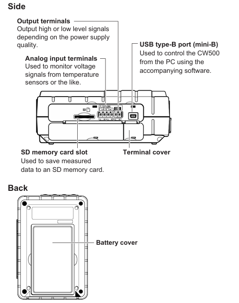
(3) Side and back
Side: SD card slot (supporting 2GB SD card), USB Type-B interface (connected to PC), analog input terminal (2-channel, ± 11VDC, monitoring temperature sensor and other signals), digital output terminal (open collector, outputting low level when power quality event triggers).
Back: Battery cover (6 AA batteries), instrument serial number label (to be provided when contacting the dealer).
2. Probe and wiring identification
Voltage probe: equipped with a safety barrier (to avoid finger crossing), connected to the tested circuit at the crocodile clip end, and connected to the instrument voltage terminal at the other end. It needs to be matched with the ID marked color (such as red connected to V1, blue connected to VN).
Clamp probe: The direction of the arrow should be consistent with the current flow direction (otherwise the polarity of the active power will reverse), supporting a range of 2A~3000A. When connecting, it should be aligned with the arrow mark on the instrument current terminal.
Basic operation process
1. Power supply mode setting
(1) Battery powered
Confirm that the instrument is powered off, use a Phillips screwdriver to open the back battery cover, and insert 6 AA alkaline batteries (or nickel hydrogen rechargeable batteries) according to polarity.
Close the battery cover and tighten the screws. After turning on, the battery icon will be displayed at the top of the screen, with 4 bars indicating full charge and 1 bar indicating low battery (needs to be replaced in a timely manner).
Attention: Nickel hydrogen batteries need to be charged with a dedicated charger, and the instrument does not support charging function; Long term disuse requires removing the battery to avoid leaking and damaging the instrument.
(2) AC power supply
Confirm that the instrument is powered off, connect one end of the power cord to the top power interface of the instrument, and plug the other end into a socket that meets local standards (100-240VAC, 50/60Hz).
After booting up, the AC power icon is displayed at the top of the screen, with a maximum power consumption of approximately 7VA.
2. Preparation before measurement
(1) Paste terminal board and ID mark
Select the input terminal board that matches the wiring color from the accessories (such as TYPE 1: VN=blue, V1=red, V2=green), clean the top terminal area of the instrument, and paste it.
Paste the ID tag on both ends of the probe to ensure consistency with the terminal color (such as connecting the red probe to the V1 terminal), to avoid wiring errors.
(2) SD card installation
Open the side SD card slot cover, insert the SD card face up (hear a "click" sound to indicate installation), and close the slot cover.
The new SD card needs to be formatted on the instrument (through the SETUP menu), as formatting on a PC may result in abnormal recording; Stop recording before removing the SD card to avoid data damage.
3. Wiring and measurement startup
Taking the "three-phase four wire (3P4W)" wiring as an example, the process is as follows:
Power off confirmation: Ensure that the tested circuit is powered off, remove the instrument power supply and probe.
Voltage wiring: Connect the voltage probe crocodile clip to VN (neutral wire) and V1/V2/V3 (phase wire) respectively, and insert the other end of the probe into the instrument VN and V1/V2/V3 terminals.
Current wiring: Clamp the clamp probe on the outside of the V1/V2/V3 phase line (arrow pointing towards the current flow direction), and insert the probe plug into the A1/A2/A3 terminals accordingly.
Power on and setup: Press and hold the power button to turn on the device, press the SETUP button to enter "Basic Setup", select the wiring system as "3P4W", confirm the voltage range (default 600V), and current clamp model (e.g. 96064 is 500A).
Start recording: Press the START button, the status LED green light stays on, the screen displays "REC", and start recording measurement data; Press the STOP button to stop recording, and the data will be automatically saved to the SD card.
4. Data display and operation
(1) Key function key operation
W/Wh key: Switch between displaying instantaneous values (voltage, current, power), integrated values (electrical energy Wh, varh), and demand values (DEM Target/Guess/Max).
Vector key: Display voltage/current vector diagram, check if the wiring phase is correct (e.g. three-phase voltage phase difference should be 120 °).
Waveform key: Display real-time voltage/current waveforms, switch channels using the directional keys, and adjust the time scale by pressing the F2 key (e.g. 5ms/div).
Harmonic key: displays the harmonic analysis results (1st to 50th harmonics), including THD (total harmonic distortion) and the percentage of voltage/current for each harmonic.
QUALITY key: displays the record of power quality events, such as the occurrence time and value of sudden rise (default 110% rated voltage), sudden drop (default 90% rated voltage), and interruption (default 10% rated voltage).
- OMRON
- ABB
- General Electric
- EMERSON
- Honeywell
- HIMA
- ALSTOM
- Rolls-Royce
- MOTOROLA
- Rockwell
- Siemens
- Woodward
- YOKOGAWA
- FOXBORO
- KOLLMORGEN
- MOOG
- KB
- YAMAHA
- BENDER
- TEKTRONIX
- Westinghouse
- AMAT
- AB
- XYCOM
- Yaskawa
- B&R
- Schneider
- KONGSBERG
- NI
- WATLOW
- ProSoft
- SEW
- ADVANCED
- Reliance
- TRICONEX
- METSO
- MAN
- Advantest
- STUDER
- DANAHER MOTION
- Bently
- Galil
- EATON
- MOLEX
- DEIF
- B&W
- ZYGO
- Aerotech
- DANFOSS
- Beijer
- Moxa
- Rexroth
- Johnson
- WAGO
- TOSHIBA
- BMCM
- SMC
- HITACHI
- HIRSCHMANN
- Application field
- XP POWER
- CTI
- TRICON
- STOBER
- Thinklogical
- Horner Automation
- Meggitt
- Fanuc
- Baldor
- SHINKAWA
- Other Brands
- UniOP
- KUKA
- Iba
- Beckhoff
-
 Basler D90 96801 100 PCB Card
 -
 Basler XR2002F Voltage Regulator (110 VAC, 48-480 Hz)
 -
 Basler SR8A-2B14B3A Regulator
 -
 Basler 9561500100 Module
 -
 Basler DECS-400 BE1-11 System
 -
 Basler DECS-100-B15 Excitation Control
 -
 Basler SCP 210 Frequency Controller
 -
 Basler SR4A-2B15B3A Static Voltage Regulator
 -
 Basler BE1-32R Power Relay
 -
 Basler PIA2400-17GM Power Interface Adapter
 -
 Basler MVC 232 Manual Voltage Control Module
 -
 Basler SSR 32-12 Static Voltage Regulator
 -
 Basler 5MW AVR Generator Voltage Regulator
 -
 Basler VR63-4B Voltage Regulator
 -
 Basler DECS-100-A05 AVR for Engine Generator
 -
 Basler DECS-100-B15 Automatic Voltage Regulator
 -
 Basler BE1-32R Directional Power Relay
 -
 Basler BE1-87B Differential Relay
 -
 Basler UFOV 260A Protective Module
 -
 Basler 9-2614-02-100 PCB Rev M
 -
Basler DECS-100-B15 Digital AVR
-
 Basler 9284900103 PS DECS-400N
 -
 Basler D4N3H1U Intertie Protection
 -
 Basler DECS-100-B15 A15 AVR
 -
 Basler KR4F Voltage Regulator
 -
 Basler BE26434 T14 Transformer
 -
 Basler SR8A-2B15B3A Regulator
 -
 Westinghouse 774B472A12 AR Relay
 -
Basler DECS-100-B15 AVR
-
Basler XR2002F Regulator 110V
-
Basler SR125-E Static Regulator
-
 Basler SSR 125-12 Regulator
 -
 Basler MOC2599 Motor Pot
 -
 Basler BE1-DFPR Feeder Relay
 -
 Basler CBS 305 Current Boost
 -
 Basler BE1-25 AutoSync
 -
 Basler MVC 300 Voltage Control
 -
 Basler BE3-25A AutoSync
 -
 Basler KR7FF Static Regulator
 -
 Basler 90-49000-100 Regulator
 -
 Basler 880 kVA Dry Type Transformer Specs
 -
 Basler Electric BE1-25 Sync-Check Relay Specs
 -
 Basler SSR 125-12 Voltage Regulator Specs
 -
 Basler Electric BE1-851 Overcurrent Relay Review
 -
Basler Electric 149D930G02 Control Sub-Assembly
-
 Basler Electric BE1-81O/UT Frequency Relay Specs
 -
 Basler Electric BE1-51/27C Overcurrent Relay
 -
 Basler Electric 149D956G02 Industrial Component
 -
Basler Electric BE1-51A Overcurrent Relay Specs
-
 Basler Electric BE1-40Q Loss of Excitation Relay
 -
 Basler DECS-200 Excitation Control System
 -
 Basler DECS-200 Voltage Regulator 56-277V AC / 125V DC
 -
Basler BE1-87T Transformer Differential Relay
-
 Basler RDP-110-S1 Protection Relay
 -
 Basler BE1-700V Digital Protective Relay
 -
 Basler BE1-951 Overcurrent Protection System
 -
 Basler DECS-300 Digital Excitation Control
 -
 Basler DECS-200 Digital Excitation Control
 -
 Basler DECS-200-1C Excitation Control System
 -
Basler DECS-200-1L Digital Excitation Control
-
 Basler Electric BE1-GPS Generator Protection System
 -
Basler Electric DECS-200-1C Digital Excitation Controller
-
 Basler Electric DECS125-15 Excitation Control with Power Module
 -
 Basler Electric BE1-87G Differential Relay
 -
 Basler Electric BE1-11 Protection System I5A3M2P2N0EA00
 -
Basler Electric DECS-200-1C Excitation Control System
-
Basler Electric BE1-11g Generator Protection Relay
-
Basler Electric DECS 125-15-B2C1 V2.0.9 Excitation Control
-
 Basler Electric BE1-81O/UT3ED1JA7N2F Frequency Relay
 -
Basler Electric BE1-81O/UT3EE1YB7N1F Frequency Relay
-
 Basler Electric DECS-200-1L Digital Excitation Control System
 -
Basler DECS125-15-B2C1 Excitation Control
-
 Basler 9507900205 SSR Retrofit Voltage Regulator
 -
 Basler BE2000E Digital Voltage Regulator
 -
 Basler BE1-GPS Generator Protection System
 -
Basler DECS-250-CN1CN1N Digital Excitation Control
-
 Basler DGC-2020 Genset Controller
 -
 Basler BE1-81O UT3ED1LA7N0F Frequency Relay (Variant)
 -
 Basler BE1-81O UT3EE1YA9S0F Frequency Relay (Variant)
 -
Basler BE1-81O Over/Under Frequency Relay
-
Basler DECS125-15 Digital Excitation Control
-
Basler Electric BE1-951 Overcurrent Protection System
-
 Basler Electric BE1-700V Digital Protective Relay
 -
 Basler Electric APR63-5 Automatic Voltage Regulator
 -
Basler Electric BE1-851 Overcurrent Protection System
-
Basler Electric DECS-250-LN1SN1N Excitation Control
-
 Basler Electric BE1-87T Transformer Differential Relay
 -
Basler Electric DECS-200-1L Excitation Control System
-
 Basler Electric 9310300100 DECS-300 Excitation Control
 -
 Basler Electric SSE-N 125-4.5KW Shunt Exciter Regulator
 -
 Basler Electric DGC-2020HD-5NS1DNSBA Genset Controller
 -
Basler Electric BE1-81-O/UT3EE1JB7N1F Frequency Relay
-
Basler Electric BE1-81T1EE1WA0N1F Frequency Relay
-
 Basler Electric BE1-25M1EA6PN5R1F Sync-Check Relay
 -
 Basler Electric BE1-GPS Generator Protection System
 -
Basler Electric DECS-250-LN1SN1N Excitation Control Rev V
-
 Basler Electric DECS-250-CN2CN1N Excitation Control
 -
Basler Electric BE1-50/51B-207 Overcurrent Relay
-
Basler Electric DECS-300-C0N0 Excitation Control System
-
Basler Electric DECS-200 Digital Excitation Control System
-
Basler Electric DECS-250-LN1CN1N Excitation Unit
-
Basler Electric DECS-250 LN2SA1D Excitation Unit Specs
-
Basler Electric BE1-87T Transformer Relay Review
-
Basler Electric BE1-11 Protection System
-
Basler Electric BE1-GPS100-E4N1H1N Protection System
-
 Allen-Bradley 442G-MABH-R Safety Module
 -
 Beckhoff CX1030-0111 PLC Assembly Profile
 -
 FANUC IC693CPU364 PLC Module
 -
 Orange Denmark Type 200816 220 PLC Specs
 -
 OMRON C200H-SNT31 Sysmac PLC Module
 -
 Allen Bradley 20AB022A3AYNANC0 PowerFlex 70
 -
 OMRON C200HW-PCU01 Position Control Unit
 -
 ABB AO845A-eA Analog Output Module
 -
 OMRON CJ1M-CPU22 CPU Unit
 -
 Allen Bradley 100-E265ED11 Contactor
 -
 Honeywell 51304511-100 Interface Module
 -
 SOLEXY BXF3S0101N0018 Gateway Module
 -
 OMRON CJ2H-CPU65 CPU Unit
 -
 Automation Direct GS2-45P0 AC Drive
 -
 M68-2000 2-Axis Motion CNC Controller
 -
 OMRON CJ1M-CPU11 V3.0 PLC CPU Unit
 -
 OMRON CJ1W-NC413 4-Axis Positioning Controller
 -
 OMRON 3G2A3-PRO16 Programming Console HMI
 -
 Siemens 3VT8440-2AA04-2GA2 Molded Case Circuit Breaker
 -
 Siemens 3RT5045 Contactor Series
 -
 OMRON C200HS-CPU01-E SYSMAC PLC Controller
 -
 OMRON C500-NC103-E Positioning Control Unit
 -
 OMRON CJ1W-TC001 Temperature Control Unit


