
YOKOGAWA CW500 Power Quality Analyzer
YOKOGAWA CW500 Power Quality Analyzer
Instrument positioning and core use
CW500 is a portable power quality analyzer that can accurately measure voltage, current, power, harmonics, and power quality events (sudden rise/fall/interruption, transient overvoltage, impulse current, flicker, etc.). It supports various wiring systems from single-phase two wire to three-phase four wire, and is widely used in power quality assessment and problem solving in factory distribution systems, new energy power stations, data centers, and other scenarios.
Core difference models: divided into two categories: with Bluetooth function (- B1, only applicable in Japan, the United States, and Canada) and without Bluetooth function (- B0). The power cord is configured according to regional standards (such as GB standards, VDE standards, etc.), and the corresponding model needs to be selected according to the usage region.
Open box inspection and accessory instructions
1. Packaging content confirmation
After unboxing, it is necessary to verify the instrument model and suffix code (such as power cord standard, Bluetooth function) to ensure consistency with the order. The core accessories are shown in the table below:
Serial number, accessory name, model/specification, quantity description
1 set of voltage probe 98078, including 4 red, white, blue, and black wires (with crocodile clip), to match the terminals according to the wiring color
According to regional standards (such as UL/CSA for - B and GB for - H), one cord with a maximum rated voltage of 250V (125V for some models) needs to be matched with local power grid standards
3 USB cables L3064AD 1 for connecting PC and instrument, supporting data transmission and remote control
4 AA alkaline batteries (LR6) with 6 spare power supplies, with a full charge range of about 3 hours (when the backlight is turned off)
5 SD memory cards 97060 (2GB), 1 card for storing measurement data, supporting FAT16 format
6 portable cases 93046 1 protective instrument from impact and dust
7 Input Terminal Board -1 piece selected by wiring color (6 types), pasted on the top terminal area of the instrument
8 ID tags with 8 colors (red/blue/yellow, etc.) are pasted on both ends of the probe, corresponding to the terminal colors, to avoid wiring errors
9 CDs -1 sheet including application software and electronic manual (PDF)
1 set of 10 manuals including IM CW500-02EN, quick start guide, installation manual, and safety manual
2. Optional accessories (purchased separately)
It mainly includes current clamp probes with different ranges (2A~3000A, such as 2A for 96060 and 3000A for 96066), power adapters (98031, CW500 specific), banana head DIN adapter cables (99073), etc. The appropriate probe should be selected according to the measurement current range.
Safety regulations and operational limitations
1. Safety symbols and warnings
Warning: Refers to the risk of fatal/serious injury, such as prohibition of use in explosive environments, prohibition of unauthorized disassembly of instruments, and power-off and removal of probes before replacing batteries.
CAUTION: It involves the risk of minor injury or equipment damage, such as avoiding short circuits at the metal end of the probe, measuring beyond the range for a long time, and using in humid environments.
Protection level: Double insulation design, measurement category in accordance with IEC61010 standard, voltage limits for different categories are as follows:
CAT IV: 300VAC (applicable to power input terminal)
CAT III: 600VAC (applicable to distribution panels, circuit breakers)
CAT II: 1000VAC (suitable for household appliances and portable tools)
2. Operating environment restrictions
Environmental conditions: working temperature 0~45 ℃, relative humidity ≤ 85% (no condensation); Storage temperature -20~60 ℃, altitude ≤ 2000m, indoor use.
Electromagnetic compatibility: Class A industrial equipment may cause radio interference when used in residential areas, and users need to solve the interference problem themselves; Compliant with standards such as EN 61326-1 and EN 55011 Class A.
Instrument structure and functional layout
1. Name and function of core components
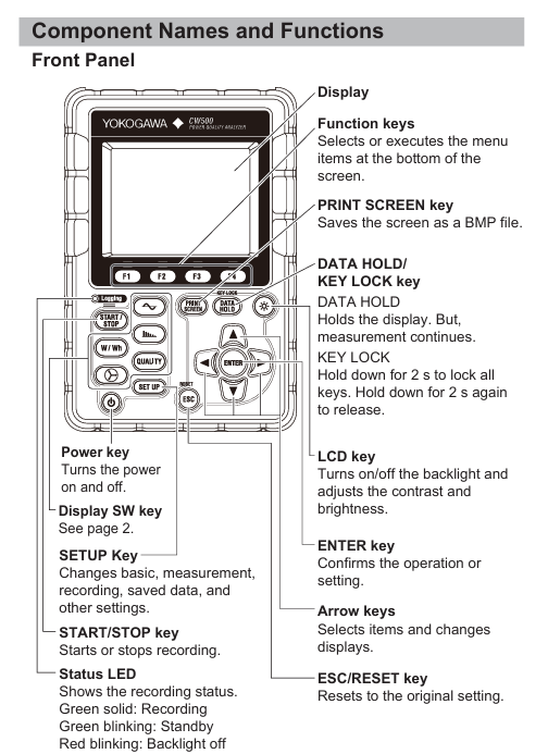
(1) Front panel
Component Function Description
Display screen 3.5-inch color TFT LCD (320 × 240 pixels), displaying measurement data, waveforms, vector graphics, etc
Function keys (F1~F4) execute menu options at the bottom of the screen, such as "Zoom", "Trend", "Customize"
The PRIMT SCREEN key saves the current screen as a BMP file to the SD card
Press and hold the DATA HOLD/KEY LOCK key for 2 seconds to lock all keys, then press and hold again to unlock; Short press to maintain display (measurement continues)
Press and hold the power button to turn on/off, and the interface from the last shutdown will be displayed after turning on
LCD key switches backlight switch, adjusts contrast and brightness
START/STOP key to start/stop data recording, status LED: green light constantly on indicates recording, green light flashing indicates standby
(2) Top terminal area
Voltage input terminals: VN (neutral wire), V1/V2/V3 (phase wire), supporting single-phase to three-phase wiring.
- OMRON
- ABB
- General Electric
- EMERSON
- Honeywell
- HIMA
- ALSTOM
- Rolls-Royce
- MOTOROLA
- Rockwell
- Siemens
- Woodward
- YOKOGAWA
- FOXBORO
- KOLLMORGEN
- MOOG
- KB
- YAMAHA
- BENDER
- TEKTRONIX
- Westinghouse
- AMAT
- AB
- XYCOM
- Yaskawa
- B&R
- Schneider
- KONGSBERG
- NI
- WATLOW
- ProSoft
- SEW
- ADVANCED
- Reliance
- TRICONEX
- METSO
- MAN
- Advantest
- STUDER
- DANAHER MOTION
- Bently
- Galil
- EATON
- MOLEX
- DEIF
- B&W
- ZYGO
- Aerotech
- DANFOSS
- Beijer
- Moxa
- Rexroth
- Johnson
- WAGO
- TOSHIBA
- BMCM
- SMC
- HITACHI
- HIRSCHMANN
- Application field
- XP POWER
- CTI
- TRICON
- STOBER
- Thinklogical
- Horner Automation
- Meggitt
- Fanuc
- Baldor
- SHINKAWA
- Other Brands
- UniOP
- KUKA
- Iba
- Beckhoff
-
 Basler D90 96801 100 PCB Card
 -
 Basler XR2002F Voltage Regulator (110 VAC, 48-480 Hz)
 -
 Basler SR8A-2B14B3A Regulator
 -
 Basler 9561500100 Module
 -
 Basler DECS-400 BE1-11 System
 -
 Basler DECS-100-B15 Excitation Control
 -
 Basler SCP 210 Frequency Controller
 -
 Basler SR4A-2B15B3A Static Voltage Regulator
 -
 Basler BE1-32R Power Relay
 -
 Basler PIA2400-17GM Power Interface Adapter
 -
 Basler MVC 232 Manual Voltage Control Module
 -
 Basler SSR 32-12 Static Voltage Regulator
 -
 Basler 5MW AVR Generator Voltage Regulator
 -
 Basler VR63-4B Voltage Regulator
 -
 Basler DECS-100-A05 AVR for Engine Generator
 -
 Basler DECS-100-B15 Automatic Voltage Regulator
 -
 Basler BE1-32R Directional Power Relay
 -
 Basler BE1-87B Differential Relay
 -
 Basler UFOV 260A Protective Module
 -
 Basler 9-2614-02-100 PCB Rev M
 -
Basler DECS-100-B15 Digital AVR
-
 Basler 9284900103 PS DECS-400N
 -
 Basler D4N3H1U Intertie Protection
 -
 Basler DECS-100-B15 A15 AVR
 -
 Basler KR4F Voltage Regulator
 -
 Basler BE26434 T14 Transformer
 -
 Basler SR8A-2B15B3A Regulator
 -
 Westinghouse 774B472A12 AR Relay
 -
Basler DECS-100-B15 AVR
-
Basler XR2002F Regulator 110V
-
Basler SR125-E Static Regulator
-
 Basler SSR 125-12 Regulator
 -
 Basler MOC2599 Motor Pot
 -
 Basler BE1-DFPR Feeder Relay
 -
 Basler CBS 305 Current Boost
 -
 Basler BE1-25 AutoSync
 -
 Basler MVC 300 Voltage Control
 -
 Basler BE3-25A AutoSync
 -
 Basler KR7FF Static Regulator
 -
 Basler 90-49000-100 Regulator
 -
 Basler 880 kVA Dry Type Transformer Specs
 -
 Basler Electric BE1-25 Sync-Check Relay Specs
 -
 Basler SSR 125-12 Voltage Regulator Specs
 -
 Basler Electric BE1-851 Overcurrent Relay Review
 -
Basler Electric 149D930G02 Control Sub-Assembly
-
 Basler Electric BE1-81O/UT Frequency Relay Specs
 -
 Basler Electric BE1-51/27C Overcurrent Relay
 -
 Basler Electric 149D956G02 Industrial Component
 -
Basler Electric BE1-51A Overcurrent Relay Specs
-
 Basler Electric BE1-40Q Loss of Excitation Relay
 -
 Basler DECS-200 Excitation Control System
 -
 Basler DECS-200 Voltage Regulator 56-277V AC / 125V DC
 -
Basler BE1-87T Transformer Differential Relay
-
 Basler RDP-110-S1 Protection Relay
 -
 Basler BE1-700V Digital Protective Relay
 -
 Basler BE1-951 Overcurrent Protection System
 -
 Basler DECS-300 Digital Excitation Control
 -
 Basler DECS-200 Digital Excitation Control
 -
 Basler DECS-200-1C Excitation Control System
 -
Basler DECS-200-1L Digital Excitation Control
-
 Basler Electric BE1-GPS Generator Protection System
 -
Basler Electric DECS-200-1C Digital Excitation Controller
-
 Basler Electric DECS125-15 Excitation Control with Power Module
 -
 Basler Electric BE1-87G Differential Relay
 -
 Basler Electric BE1-11 Protection System I5A3M2P2N0EA00
 -
Basler Electric DECS-200-1C Excitation Control System
-
Basler Electric BE1-11g Generator Protection Relay
-
Basler Electric DECS 125-15-B2C1 V2.0.9 Excitation Control
-
 Basler Electric BE1-81O/UT3ED1JA7N2F Frequency Relay
 -
Basler Electric BE1-81O/UT3EE1YB7N1F Frequency Relay
-
 Basler Electric DECS-200-1L Digital Excitation Control System
 -
Basler DECS125-15-B2C1 Excitation Control
-
 Basler 9507900205 SSR Retrofit Voltage Regulator
 -
 Basler BE2000E Digital Voltage Regulator
 -
 Basler BE1-GPS Generator Protection System
 -
Basler DECS-250-CN1CN1N Digital Excitation Control
-
 Basler DGC-2020 Genset Controller
 -
 Basler BE1-81O UT3ED1LA7N0F Frequency Relay (Variant)
 -
 Basler BE1-81O UT3EE1YA9S0F Frequency Relay (Variant)
 -
Basler BE1-81O Over/Under Frequency Relay
-
Basler DECS125-15 Digital Excitation Control
-
Basler Electric BE1-951 Overcurrent Protection System
-
 Basler Electric BE1-700V Digital Protective Relay
 -
 Basler Electric APR63-5 Automatic Voltage Regulator
 -
Basler Electric BE1-851 Overcurrent Protection System
-
Basler Electric DECS-250-LN1SN1N Excitation Control
-
 Basler Electric BE1-87T Transformer Differential Relay
 -
Basler Electric DECS-200-1L Excitation Control System
-
 Basler Electric 9310300100 DECS-300 Excitation Control
 -
 Basler Electric SSE-N 125-4.5KW Shunt Exciter Regulator
 -
 Basler Electric DGC-2020HD-5NS1DNSBA Genset Controller
 -
Basler Electric BE1-81-O/UT3EE1JB7N1F Frequency Relay
-
Basler Electric BE1-81T1EE1WA0N1F Frequency Relay
-
 Basler Electric BE1-25M1EA6PN5R1F Sync-Check Relay
 -
 Basler Electric BE1-GPS Generator Protection System
 -
Basler Electric DECS-250-LN1SN1N Excitation Control Rev V
-
 Basler Electric DECS-250-CN2CN1N Excitation Control
 -
Basler Electric BE1-50/51B-207 Overcurrent Relay
-
Basler Electric DECS-300-C0N0 Excitation Control System
-
Basler Electric DECS-200 Digital Excitation Control System
-
Basler Electric DECS-250-LN1CN1N Excitation Unit
-
Basler Electric DECS-250 LN2SA1D Excitation Unit Specs
-
Basler Electric BE1-87T Transformer Relay Review
-
Basler Electric BE1-11 Protection System
-
Basler Electric BE1-GPS100-E4N1H1N Protection System
-
 Allen-Bradley 442G-MABH-R Safety Module
 -
 Beckhoff CX1030-0111 PLC Assembly Profile
 -
 FANUC IC693CPU364 PLC Module
 -
 Orange Denmark Type 200816 220 PLC Specs
 -
 OMRON C200H-SNT31 Sysmac PLC Module
 -
 Allen Bradley 20AB022A3AYNANC0 PowerFlex 70
 -
 OMRON C200HW-PCU01 Position Control Unit
 -
 ABB AO845A-eA Analog Output Module
 -
 OMRON CJ1M-CPU22 CPU Unit
 -
 Allen Bradley 100-E265ED11 Contactor
 -
 Honeywell 51304511-100 Interface Module
 -
 SOLEXY BXF3S0101N0018 Gateway Module
 -
 OMRON CJ2H-CPU65 CPU Unit
 -
 Automation Direct GS2-45P0 AC Drive
 -
 M68-2000 2-Axis Motion CNC Controller
 -
 OMRON CJ1M-CPU11 V3.0 PLC CPU Unit
 -
 OMRON CJ1W-NC413 4-Axis Positioning Controller
 -
 OMRON 3G2A3-PRO16 Programming Console HMI
 -
 Siemens 3VT8440-2AA04-2GA2 Molded Case Circuit Breaker
 -
 Siemens 3RT5045 Contactor Series
 -
 OMRON C200HS-CPU01-E SYSMAC PLC Controller
 -
 OMRON C500-NC103-E Positioning Control Unit
 -
 OMRON CJ1W-TC001 Temperature Control Unit


