
Foxboro Evo ™ Compact 200 Series I/O subsystem of the system
Core function: Provides analog measurement, digital sensing, analog/discrete control capabilities, supporting continuous, batch, and discrete control solutions
Compatibility: Fully compatible with existing I/A Series ® The system's 200 Series I/O devices and traditional 100 Series I/O devices support upgrading and replacing existing standard 200 Series subsystems
Core value: Distributed deployment reduces on-site wiring, trunking, and conduit installation costs, and adapts to the flexible deployment needs of industrial scenarios
Foxboro Evo ™ Compact 200 Series I/O subsystem of the system
System core positioning and compatibility
Product ownership: Foxboro Evo ™ Compact 200 Series I/O subsystem for process automation systems, launched by Schneider Electric
Core function: Provides analog measurement, digital sensing, analog/discrete control capabilities, supporting continuous, batch, and discrete control solutions
Compatibility: Fully compatible with existing I/A Series ® The system's 200 Series I/O devices and traditional 100 Series I/O devices support upgrading and replacing existing standard 200 Series subsystems
Core value: Distributed deployment reduces on-site wiring, trunking, and conduit installation costs, and adapts to the flexible deployment needs of industrial scenarios
Core Components and Classification
Component type, key product, core function, key parameters
Control processor FCP280 200/100 Series FBMs control interface, supporting 4 HDLC buses and up to 128 FBMs
FCP270 is compatible with dual baud rates (2Mbps/268Kbps) and requires FBI100 to adapt to 100 Series. It supports 32 200 Series FBMs without FEM100
ZCP270 is compatible with 100 Series racks and supports up to 128 FBMs per module through FCMs communication
Fieldbus Modules (FBMs) Analog Input Class FBM201 (0-20mA), FBM214b (HART) ® Input channel isolation/differential isolation, 8-32 channels
Analog output class FBM215 (HART) ® Output), FBM237 (redundant 0-20mA) and other fail safe configurations (hold/fallback), 4-8 channels
Discrete I/O class FBM217 (32 channel input), FBM219 (24DI+8DO) and other group isolation/channel isolation, 8-32 channels
Hybrid I/O classes such as FBM227 (analog+discrete) and FBM247 (current/voltage/pulse) support HART ®、 Multi signal type adaptation
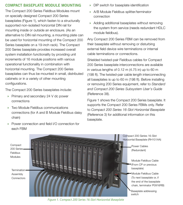
Auxiliary component base plate 16 slot horizontal base plate (RH101AA) supports 16 FBMs, DIN rail/19 inch rack installation
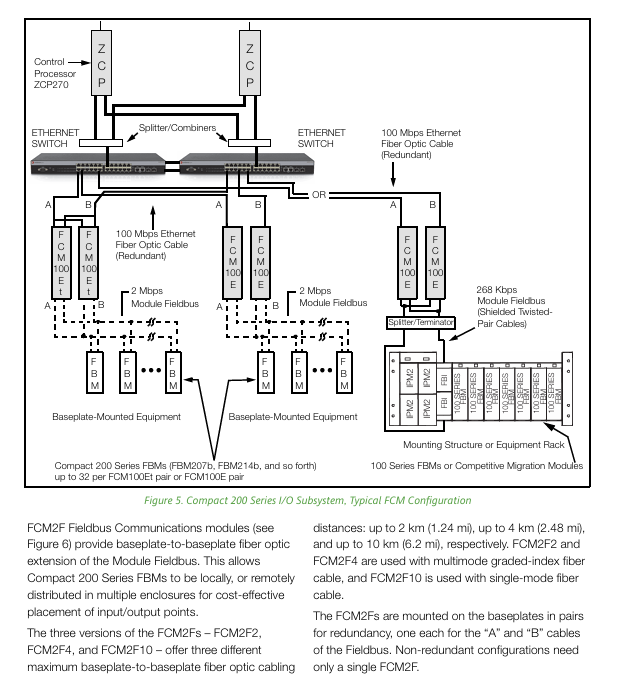
Communication module FCM100E/Et (fiber to bus conversion), FCM2F (fiber extension) FCM2F supports up to 10km single-mode fiber
Isolator FBI200 extends bus distance to 305m, isolation filtering
Shell G/K series G13/G14 (system/terminal shell), K13/K14 IP43/54 protection, suitable for ordinary/harsh environments
Key technical characteristics and advantages
performance
The analog input adopts SigmaDelta fast integration ADC, with an update speed of up to 25ms, suitable for high-speed regulation and control
Built in configurable moving average filter effectively removes electromagnetic noise
System communication speed: 100Mbps Ethernet (control network), 2Mbps/268Kbps HDLC module bus
Reliability Design
Integrating logic functions into a single ASIC chip reduces the number, volume, heat dissipation, and cost of components
Single module availability 0.999974 (redundant power supply+2-hour MTTR), redundant module availability 0.9999964
Optional redundancy: power supply, control network FCMs、 Control processors, module bus cables, and some FBMs
Deployment flexibility
Compact size: 1 16 slot compact base plate+16 FBMs space<2 standard 200 Series base plates+16 standard FBMs
Installation method: Horizontal DIN rail installation or 19 inch rack installation, supporting distributed small cabinet deployment
Cable length: shielded twisted pair 0.12-60m, fiber optic extension up to 20km (2 pairs of FCM2F10)
environmental adaptability
Pollution protection: Class G3 (ISA S71.04), suitable for harsh industrial pollution environments
Working temperature: FBMs up to 60 ℃ (140 ° F)
Safety certifications: UL (US Canada), ATEX (Explosion proof), CE (Low Voltage/EMC/ATEX Directive), RoHS compliance
System configuration and upgrade requirements
configuration scheme
Pure compact chassis configuration: only using Compact 200 Series chassis
Mixed configuration: Compact mixed with standard 200 Series baseboard (supports compact in front/back)
Maximum scale: Up to 32 FBMs per single bottom chain, 4 bottom chains supported per FCP280
Upgrade requirements
Space requirement: The installation location should have sufficient horizontal DIN rails
Power Requirements: Supports FPS480-24/FPS400-24/FPS220-24/FPS120-24 power supplies
Cooling requirement: 1 fan tray is required for every 2 adjacent compact baseboards (1 for each baseboard when deployed separately)
Cable replacement: The terminal cable of the standard 200 Series FBMs needs to be replaced with a Compact series adapter cable
Electrical and safety regulations
Grounding requirements: comply with IEC 61000-5-1/5-2 standard (or regional equivalent standard)
Power configuration: 24V DC power supply, supports single/redundant power distribution, triggers icon color change, system alarm, and print notification in case of power failure
Isolation level: FBMs support channel isolation, differential isolation, and group isolation, with some terminal components (TA) providing additional channel isolation
Wiring characteristics: FBMs are hot swappable and do not affect external field device wiring and internal cable connections
Key questions and answers
Question 1: What are the core advantages of the Compact 200 Series I/O subsystem? What scenarios are applicable?
Answer: The core advantages are concentrated in three points: ① High reliability and availability, achieved through ASIC integrated design with high availability of single module 0.999974 and redundant module 0.9999964, suitable for continuous operation requirements; ② Flexible deployment and compact design, with a volume only half of the standard 200 Series, supporting distributed DIN rail/rack installation, reducing wiring costs; ③ Strong environmental adaptability and compatibility, Class G3 pollution protection, 60 ℃ high temperature tolerance, and compatibility with existing 100/200 Series I/O devices, supporting seamless system upgrades. Applicable scenarios include: continuous/batch/discrete control tasks in industrial sites, harsh polluted environments (such as chemical and metallurgical industries), large factories that require remote distributed deployment, and existing I/A Series ® System upgrade project.
Question 2: What are the core components of this subsystem? What are the differences in the carrying capacity of FBMs with different control processors?
Answer: The core components include: ① Control processor (FCP280/FCP270/ZCP270); ② 20+FBMs (analog/digital/hybrid I/O types); ③ 16 slot horizontal bottom plate, FBI200 isolator, FCM communication module; ④ G/K series protective casing and terminal components (TA). The differences in the carrying capacity of FBMs among different processors are as follows:
FCP280: Supports up to 128 200 Series FBMs, or 128 (100+200 Series) hybrid FBMs (up to 64 for 100 Series);
FCP270: Up to 32 200 Series FBMs without FEM100, up to 128 with FEM100, and up to 64 with 100 Series;
ZCP270: Supports up to 128 FBMs (100/200 Series) through FCM100E, with a single FCM100Et pair supporting 32 FBMs.
Question 3: What are the components of the system's redundant configuration? What is the cable length limit during deployment?
Answer: ① Redundant configuration coverage: power supply, control network, FCMs (communication modules), control processors, module bus cables, and some FBMs (such as FBM216b/FBM218); Redundant design can avoid single point failures and ensure the continuous operation of critical process circuits. ② Cable length limit:
Shielded twisted pair cable (module bus/backplane interconnection): 0.12-60m (single segment), total length of the entire 2Mbps HDLC bus ≤ 60m (including FBI200 connection);
Fiber optic cables (FCM2F series): FCM2F2 (2km), FCM2F4 (4km), FCM2F10 (10km), 2 pairs of FCM2F10 can be extended up to 20km;
Terminal Assembly (TA) and Base Plate Connection Cable: 0.5-30m.
- OMRON
- ABB
- General Electric
- EMERSON
- Honeywell
- HIMA
- ALSTOM
- Rolls-Royce
- MOTOROLA
- Rockwell
- Siemens
- Woodward
- YOKOGAWA
- FOXBORO
- KOLLMORGEN
- MOOG
- KB
- YAMAHA
- BENDER
- TEKTRONIX
- Westinghouse
- AMAT
- AB
- XYCOM
- Yaskawa
- B&R
- Schneider
- KONGSBERG
- NI
- WATLOW
- ProSoft
- SEW
- ADVANCED
- Reliance
- TRICONEX
- METSO
- MAN
- Advantest
- STUDER
- DANAHER MOTION
- Bently
- Galil
- EATON
- MOLEX
- DEIF
- B&W
- ZYGO
- Aerotech
- DANFOSS
- Beijer
- Moxa
- Rexroth
- Johnson
- WAGO
- TOSHIBA
- BMCM
- SMC
- HITACHI
- HIRSCHMANN
- Application field
- XP POWER
- CTI
- TRICON
- STOBER
- Thinklogical
- Horner Automation
- Meggitt
- Fanuc
- Baldor
- SHINKAWA
- Other Brands
- UniOP
- KUKA
- Iba
- Beckhoff
-
 Basler D90 96801 100 PCB Card
 -
 Basler XR2002F Voltage Regulator (110 VAC, 48-480 Hz)
 -
 Basler SR8A-2B14B3A Regulator
 -
 Basler 9561500100 Module
 -
 Basler DECS-400 BE1-11 System
 -
 Basler DECS-100-B15 Excitation Control
 -
 Basler SCP 210 Frequency Controller
 -
 Basler SR4A-2B15B3A Static Voltage Regulator
 -
 Basler BE1-32R Power Relay
 -
 Basler PIA2400-17GM Power Interface Adapter
 -
 Basler MVC 232 Manual Voltage Control Module
 -
 Basler SSR 32-12 Static Voltage Regulator
 -
 Basler 5MW AVR Generator Voltage Regulator
 -
 Basler VR63-4B Voltage Regulator
 -
 Basler DECS-100-A05 AVR for Engine Generator
 -
 Basler DECS-100-B15 Automatic Voltage Regulator
 -
 Basler BE1-32R Directional Power Relay
 -
 Basler BE1-87B Differential Relay
 -
 Basler UFOV 260A Protective Module
 -
 Basler 9-2614-02-100 PCB Rev M
 -
Basler DECS-100-B15 Digital AVR
-
 Basler 9284900103 PS DECS-400N
 -
 Basler D4N3H1U Intertie Protection
 -
 Basler DECS-100-B15 A15 AVR
 -
 Basler KR4F Voltage Regulator
 -
 Basler BE26434 T14 Transformer
 -
 Basler SR8A-2B15B3A Regulator
 -
 Westinghouse 774B472A12 AR Relay
 -
Basler DECS-100-B15 AVR
-
Basler XR2002F Regulator 110V
-
Basler SR125-E Static Regulator
-
 Basler SSR 125-12 Regulator
 -
 Basler MOC2599 Motor Pot
 -
 Basler BE1-DFPR Feeder Relay
 -
 Basler CBS 305 Current Boost
 -
 Basler BE1-25 AutoSync
 -
 Basler MVC 300 Voltage Control
 -
 Basler BE3-25A AutoSync
 -
 Basler KR7FF Static Regulator
 -
 Basler 90-49000-100 Regulator
 -
 Basler 880 kVA Dry Type Transformer Specs
 -
 Basler Electric BE1-25 Sync-Check Relay Specs
 -
 Basler SSR 125-12 Voltage Regulator Specs
 -
 Basler Electric BE1-851 Overcurrent Relay Review
 -
Basler Electric 149D930G02 Control Sub-Assembly
-
 Basler Electric BE1-81O/UT Frequency Relay Specs
 -
 Basler Electric BE1-51/27C Overcurrent Relay
 -
 Basler Electric 149D956G02 Industrial Component
 -
Basler Electric BE1-51A Overcurrent Relay Specs
-
 Basler Electric BE1-40Q Loss of Excitation Relay
 -
 Basler DECS-200 Excitation Control System
 -
 Basler DECS-200 Voltage Regulator 56-277V AC / 125V DC
 -
Basler BE1-87T Transformer Differential Relay
-
 Basler RDP-110-S1 Protection Relay
 -
 Basler BE1-700V Digital Protective Relay
 -
 Basler BE1-951 Overcurrent Protection System
 -
 Basler DECS-300 Digital Excitation Control
 -
 Basler DECS-200 Digital Excitation Control
 -
 Basler DECS-200-1C Excitation Control System
 -
Basler DECS-200-1L Digital Excitation Control
-
 Basler Electric BE1-GPS Generator Protection System
 -
Basler Electric DECS-200-1C Digital Excitation Controller
-
 Basler Electric DECS125-15 Excitation Control with Power Module
 -
 Basler Electric BE1-87G Differential Relay
 -
 Basler Electric BE1-11 Protection System I5A3M2P2N0EA00
 -
Basler Electric DECS-200-1C Excitation Control System
-
Basler Electric BE1-11g Generator Protection Relay
-
Basler Electric DECS 125-15-B2C1 V2.0.9 Excitation Control
-
 Basler Electric BE1-81O/UT3ED1JA7N2F Frequency Relay
 -
Basler Electric BE1-81O/UT3EE1YB7N1F Frequency Relay
-
 Basler Electric DECS-200-1L Digital Excitation Control System
 -
Basler DECS125-15-B2C1 Excitation Control
-
 Basler 9507900205 SSR Retrofit Voltage Regulator
 -
 Basler BE2000E Digital Voltage Regulator
 -
 Basler BE1-GPS Generator Protection System
 -
Basler DECS-250-CN1CN1N Digital Excitation Control
-
 Basler DGC-2020 Genset Controller
 -
 Basler BE1-81O UT3ED1LA7N0F Frequency Relay (Variant)
 -
 Basler BE1-81O UT3EE1YA9S0F Frequency Relay (Variant)
 -
Basler BE1-81O Over/Under Frequency Relay
-
Basler DECS125-15 Digital Excitation Control
-
Basler Electric BE1-951 Overcurrent Protection System
-
 Basler Electric BE1-700V Digital Protective Relay
 -
 Basler Electric APR63-5 Automatic Voltage Regulator
 -
Basler Electric BE1-851 Overcurrent Protection System
-
Basler Electric DECS-250-LN1SN1N Excitation Control
-
 Basler Electric BE1-87T Transformer Differential Relay
 -
Basler Electric DECS-200-1L Excitation Control System
-
 Basler Electric 9310300100 DECS-300 Excitation Control
 -
 Basler Electric SSE-N 125-4.5KW Shunt Exciter Regulator
 -
 Basler Electric DGC-2020HD-5NS1DNSBA Genset Controller
 -
Basler Electric BE1-81-O/UT3EE1JB7N1F Frequency Relay
-
Basler Electric BE1-81T1EE1WA0N1F Frequency Relay
-
 Basler Electric BE1-25M1EA6PN5R1F Sync-Check Relay
 -
 Basler Electric BE1-GPS Generator Protection System
 -
Basler Electric DECS-250-LN1SN1N Excitation Control Rev V
-
 Basler Electric DECS-250-CN2CN1N Excitation Control
 -
Basler Electric BE1-50/51B-207 Overcurrent Relay
-
Basler Electric DECS-300-C0N0 Excitation Control System
-
Basler Electric DECS-200 Digital Excitation Control System
-
Basler Electric DECS-250-LN1CN1N Excitation Unit
-
Basler Electric DECS-250 LN2SA1D Excitation Unit Specs
-
Basler Electric BE1-87T Transformer Relay Review
-
Basler Electric BE1-11 Protection System
-
Basler Electric BE1-GPS100-E4N1H1N Protection System
-
 Allen-Bradley 442G-MABH-R Safety Module
 -
 Beckhoff CX1030-0111 PLC Assembly Profile
 -
 FANUC IC693CPU364 PLC Module
 -
 Orange Denmark Type 200816 220 PLC Specs
 -
 OMRON C200H-SNT31 Sysmac PLC Module
 -
 Allen Bradley 20AB022A3AYNANC0 PowerFlex 70
 -
 OMRON C200HW-PCU01 Position Control Unit
 -
 ABB AO845A-eA Analog Output Module
 -
 OMRON CJ1M-CPU22 CPU Unit
 -
 Allen Bradley 100-E265ED11 Contactor
 -
 Honeywell 51304511-100 Interface Module
 -
 SOLEXY BXF3S0101N0018 Gateway Module
 -
 OMRON CJ2H-CPU65 CPU Unit
 -
 Automation Direct GS2-45P0 AC Drive
 -
 M68-2000 2-Axis Motion CNC Controller
 -
 OMRON CJ1M-CPU11 V3.0 PLC CPU Unit
 -
 OMRON CJ1W-NC413 4-Axis Positioning Controller
 -
 OMRON 3G2A3-PRO16 Programming Console HMI
 -
 Siemens 3VT8440-2AA04-2GA2 Molded Case Circuit Breaker
 -
 Siemens 3RT5045 Contactor Series
 -
 OMRON C200HS-CPU01-E SYSMAC PLC Controller
 -
 OMRON C500-NC103-E Positioning Control Unit
 -
 OMRON CJ1W-TC001 Temperature Control Unit


