
YASKAWA GA500 series AC micro frequency converter
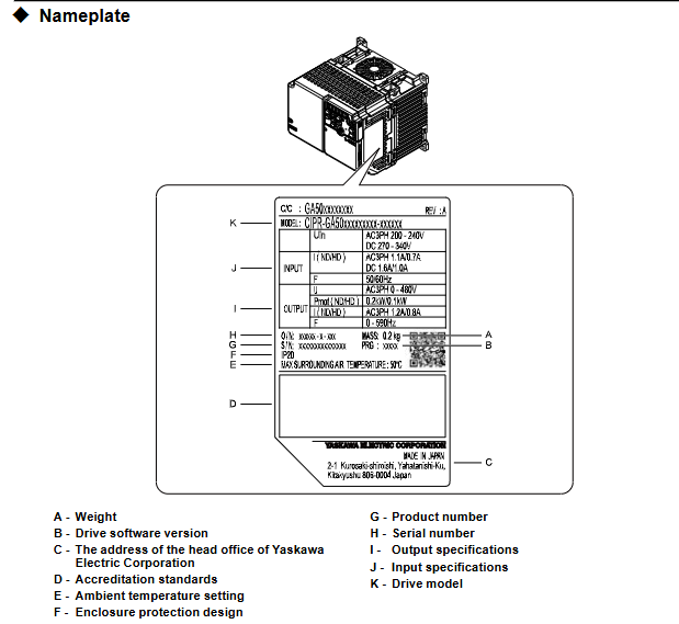
Model identification: CIPR-GA50Cxxxxxxxx, core specifications are classified as follows:
Voltage level, input type, power range, key parameters
200V single-phase 0.1-4.0 kW Max
200V C three-phase 0.1-22kW speed control range 1:40~1:100
400V level three-phase 0.37-30 kW protection level IP20/UL open type
Core features: Supports 5 control modes, compatible with induction motors, PM motors (including IPM/SPM), and synchronous reluctance motors (SynRM), with functions such as automatic tuning, energy saving, and dynamic braking.
Wiring requirements:
Wire type: Shielded twisted pair cables are required for control circuits to avoid electromagnetic interference;
Length limit: Control circuit wiring ≤ 50m, Safe Disable input wiring ≤ 30m;
Isolation requirements: The distance between the control circuit and the main circuit should be ≥ 30cm, avoiding parallel wiring, and the shielding layer should be grounded at one end (driver side).
(3) Special wiring precautions
Braking resistor: can only be connected to terminals B1 and B2, and+1 or - terminals are prohibited. ERF type braking resistors need to be set with parameter L8-01=1;
EMC filter: The built-in filter model (suffix E) needs to be grounded to the neutral line, otherwise it may cause leakage exceeding the standard;
Lightning protection and surge: MCCB (molded case circuit breaker) or RCM/RCD (residual current monitor) should be installed at the input end to avoid short circuit and surge damage.
Startup and Debugging Process
1. Operation preparation
(1) Parameter settings
General Setting Mode (SrUP): Contains 26 core parameters, including control mode (A1-02), acceleration and deceleration time (C1-01/C1-02), motor rated parameters (E2-01~E2-04), load type (C6-01), etc., suitable for quick configuration;
Application Preset (A1-06): To automatically optimize parameters for specific scenarios such as fans, pumps, and cranes, it is necessary to first initialize the parameters through A1-03 (2-wire/3-wire system);
Parameter backup and recovery: Parameters can be backed up locally through the keyboard, and can be quickly written when changing drives to avoid duplicate configurations.
(2) Keyboard operation
Mode switching: LOCAL (keyboard control)/REMOTE (external control) can be switched through the LO/RE keys. Before switching, ensure that there are no running commands to avoid sudden startup;
Core button functions:
RUN/STOP: Start/Stop, STOP key has the highest priority (can be disabled through o2-02);
Arrow keys: adjust parameter values or switch menus;
ESC/ENTER: Return to the previous menu/confirm parameter settings;
RESET: Reset the fault (the cause of the fault needs to be eliminated first).
2. Auto Tuning
(1) Tuning type and applicable scenarios
Core Requirements for Parameter Setting of Motor Type Tuning Method
Induction motor rotation tuning T1-01=0, motor disconnected from load, load rate ≤ 30%, motor nameplate parameters need to be input
Induction motor static tuning T1-01=1. The motor cannot rotate. During the tuning period, the motor does not rotate without power and only detects electrical parameters
Induction motor inter line resistance tuning T1-01=2 wiring distance exceeds 50m, compensating for the influence of line resistance
PM motor rotation tuning T2-01=4 motor disengages load, automatically detects stator resistance, d/q-axis inductance and other parameters
PM motor static tuning T2-01=1 motor fixed, suitable for scenarios where the load cannot be disconnected
PM motor high-frequency injection tuning T2-01=5 is only applicable to IPM motors, and the motor nameplate parameters need to be input first
Control circuit deceleration rate tuning T3-00=2 automatically optimizes deceleration time to prevent overvoltage faults
Control circuit KEB tuning T3-00=3 optimizes dynamic braking parameters and adapts to KEB Ride Thru function
(2) Tuning operation steps
Input the motor nameplate parameters (rated power, voltage, current, number of poles, fundamental frequency);
Confirm that the motor is disconnected from the load (rotation tuning) or firmly fixed (static tuning);
Enter Auto Tuning mode (AfUn) through the keyboard and select the corresponding tuning type;
Start tuning, during the rotation tuning period, the motor will rotate (at a speed of about 50% of the rated speed), and personnel are prohibited from approaching;
After tuning is completed, the system automatically updates the motor parameters, and the modification results can be viewed through the Verify menu.
3. Test Run
(1) No load test
Operation process: Set the frequency to 6Hz → Start the driver → Gradually increase the rated frequency (10Hz each time) → Observe the motor status;
Inspection items: Motor direction (if incorrect, replace U/T1 and V/T2 wiring), vibration (no abnormal shaking), output current (≤ 30% of rated current), no abnormal noise.
(2) Load testing
Operation process: Connect the load → Set the actual operating frequency → Start the driver → Run continuously for more than 30 minutes;
Inspection items: acceleration/deceleration response (no lag), torque output (meeting load requirements), driver temperature (≤ 85 ℃), parameter stability (no drift);
Fine tuning optimization: If vibration occurs, adjust n1-02 (anti oscillation gain), if torque is insufficient, adjust C4-01 (torque compensation gain), and if overvoltage occurs, extend deceleration time (C1-02).
(3) Test Run Checklist
Power supply voltage: The input voltage is within the allowable range on the driver nameplate;
Wiring correctness: The phase sequence of the main circuit and the polarity of the control circuit signal are correct;
Protection function: Simulate overload and overcurrent scenarios, the driver needs to trigger protection and alarm normally;
- OMRON
- ABB
- General Electric
- EMERSON
- Honeywell
- HIMA
- ALSTOM
- Rolls-Royce
- MOTOROLA
- Rockwell
- Siemens
- Woodward
- YOKOGAWA
- FOXBORO
- KOLLMORGEN
- MOOG
- KB
- YAMAHA
- BENDER
- TEKTRONIX
- Westinghouse
- AMAT
- AB
- XYCOM
- Yaskawa
- B&R
- Schneider
- KONGSBERG
- NI
- WATLOW
- ProSoft
- SEW
- ADVANCED
- Reliance
- TRICONEX
- METSO
- MAN
- Advantest
- STUDER
- DANAHER MOTION
- Bently
- Galil
- EATON
- MOLEX
- DEIF
- B&W
- ZYGO
- Aerotech
- DANFOSS
- Beijer
- Moxa
- Rexroth
- Johnson
- WAGO
- TOSHIBA
- BMCM
- SMC
- HITACHI
- HIRSCHMANN
- Application field
- XP POWER
- CTI
- TRICON
- STOBER
- Thinklogical
- Horner Automation
- Meggitt
- Fanuc
- Baldor
- SHINKAWA
- Other Brands
- UniOP
- KUKA
- Iba
- Beckhoff
-
 Basler DECS-200-2L Digital Excitation Control
 -
 Basler BE1-47N Voltage Phase Sequence Relay
 -
 Basler AEC63-7 Analog Excitation Controller 220-277V
 -
 Basler BE1-50/51B-107 Overcurrent Relay
 -
 Basler Electric BE1‑32R BE1‑E1P‑BON0F Protective Relay
 -
 Basler BE1-25 Solid State Time Overcurrent Relay M1EA6PA5S1F
 -
 Basler MVC 232 Manual Voltage Control Module 90 37000 103 60VAC 55VDC
 -
 Basler RAL6144-16GM Racer GigE Line Scan Camera
 -
 Basler SSR 63-12 Static Voltage Regulator
 -
 Basler BE1-51A Overcurrent Relay
 -
 Basler BE1-87T Solid State Protective Relay
 -
 Basler SR4A2B01B3A Static Voltage Regulator
 -
 Basler SSR 32-12 Static Voltage Regulator
 -
 Basler TRR00696 Transformer 1KVA 115V
 -
 Basler DECS-100-B15 AVR Replacement
 -
Basler BE1-27 Under-Voltage Relay
-
 Basler ACA2000-50GM Interface Module
 -
 Basler AEC63-7 Analog Excitation Controller
 -
 Basler PRS 250 Veri-Sync Relay
 -
 Basler SR4A-2B15B3A Static Voltage Regulator
 -
Basler BE1-32R Power Relay
-
Basler SR8A-2B06B3E Static Voltage Regulator
-
Basler BE1-81 O/U Frequency Relay
-
 Basler BE1-51A-K2E-W6M-B1N0F Overcurrent Relay
 -
Basler BE1-851 Overcurrent Relay G3A1S1 – 48-125V AC/DC
-
 Basler BEI-51 Overcurrent Relay – NSN 5945-01-293-2363
 -
Basler Electric L301KC Protective Relay – L301KC
-
 Basler DECS-100-B15 Automatic Voltage Regulator – Generator AVR
 -
 Basler SR4A-2B15B3A Static Voltage Regulator – SR4A2B15B3A
 -
 Basler UF 312 Under Frequency Protective Module – 9094700100
 -
Basler Electric MVC 232 Manual Control Module – 60VAC 55VDC 20A
-
Basler PRS 250 Veri-Sync Relay – Generator Synchronizing Relay
-
 Basler DECS-100-A05 Digital Regulator Review
 -
 Basler AEM-2020 Analog Expansion Module Specs
 -
 Basler DECS-100-B15 Digital Excitation Specs
 -
Basler Electric 9125600106 Regulator Component
-
Basler BE1-51A-K1E-W6M-B1N0F Overcurrent Relay
-
 Basler MVC-301 MVC 300 Excitation Controller
 -
 Basler SSR 32-12 Static Voltage Regulator
 -
 Basler 9-2849-00-101 Control Module
 -
Basler BE1-51A Overcurrent Relay
-
 Basler BE1-51/27R Overcurrent Relay
 -
 Basler BE1-51 Overcurrent Relay
 -
 Basler SR8A-2B15B3A Static Voltage Regulator
 -
 Basler BE32965001 Transformer and Timer Board
 -
 Basler 9174700100 EL200-7 Excitation Limiter
 -
 Basler BE2000E AVR Voltage Regulator
 -
Basler BE1-87G Differential Relay
-
 Basler BE21834001 Generator Control Module
 -
Basler DECS-100-B15 AVR
-
 Basler D90 96801 100 PCB Card
 -
 Basler XR2002F Voltage Regulator (110 VAC, 48-480 Hz)
 -
 Basler SR8A-2B14B3A Regulator
 -
 Basler 9561500100 Module
 -
 Basler DECS-400 BE1-11 System
 -
 Basler DECS-100-B15 Excitation Control
 -
 Basler SCP 210 Frequency Controller
 -
Basler SR4A-2B15B3A Static Voltage Regulator
-
Basler BE1-32R Power Relay
-
 Basler PIA2400-17GM Power Interface Adapter
 -
 Basler MVC 232 Manual Voltage Control Module
 -
 Basler SSR 32-12 Static Voltage Regulator
 -
Basler 5MW AVR Generator Voltage Regulator
-
 Basler VR63-4B Voltage Regulator
 -
Basler DECS-100-A05 AVR for Engine Generator
-
Basler DECS-100-B15 Automatic Voltage Regulator
-
Basler BE1-32R Directional Power Relay
-
Basler BE1-87B Differential Relay
-
 Basler UFOV 260A Protective Module
 -
 Basler 9-2614-02-100 PCB Rev M
 -
Basler DECS-100-B15 Digital AVR
-
 Basler 9284900103 PS DECS-400N
 -
 Basler D4N3H1U Intertie Protection
 -
 Basler DECS-100-B15 A15 AVR
 -
 Basler KR4F Voltage Regulator
 -
 Basler BE26434 T14 Transformer
 -
 Basler SR8A-2B15B3A Regulator
 -
 Westinghouse 774B472A12 AR Relay
 -
Basler DECS-100-B15 AVR
-
Basler XR2002F Regulator 110V
-
Basler SR125-E Static Regulator
-
Basler SSR 125-12 Regulator
-
Basler MOC2599 Motor Pot
-
 Basler BE1-DFPR Feeder Relay
 -
 Basler CBS 305 Current Boost
 -
Basler BE1-25 AutoSync
-
Basler MVC 300 Voltage Control
-
 Basler BE3-25A AutoSync
 -
 Basler KR7FF Static Regulator
 -
Basler 90-49000-100 Regulator
-
 Basler 880 kVA Dry Type Transformer Specs
 -
Basler Electric BE1-25 Sync-Check Relay Specs
-
 Basler SSR 125-12 Voltage Regulator Specs
 -
 Basler Electric BE1-851 Overcurrent Relay Review
 -
Basler Electric 149D930G02 Control Sub-Assembly
-
 Basler Electric BE1-81O/UT Frequency Relay Specs
 -
 Basler Electric BE1-51/27C Overcurrent Relay
 -
 Basler Electric 149D956G02 Industrial Component
 -
Basler Electric BE1-51A Overcurrent Relay Specs
-
 Basler Electric BE1-40Q Loss of Excitation Relay
 -
Basler DECS-200 Excitation Control System
-
 Basler DECS-200 Voltage Regulator 56-277V AC / 125V DC
 -
Basler BE1-87T Transformer Differential Relay
-
 Basler RDP-110-S1 Protection Relay
 -
 Basler BE1-700V Digital Protective Relay
 -
 Basler BE1-951 Overcurrent Protection System
 -
 Basler DECS-300 Digital Excitation Control
 -
 Basler DECS-200 Digital Excitation Control
 -
 Basler DECS-200-1C Excitation Control System
 -
Basler DECS-200-1L Digital Excitation Control
-
 Basler Electric BE1-GPS Generator Protection System
 -
Basler Electric DECS-200-1C Digital Excitation Controller
-
 Basler Electric DECS125-15 Excitation Control with Power Module
 -
Basler Electric BE1-87G Differential Relay
-
 Basler Electric BE1-11 Protection System I5A3M2P2N0EA00
 -
Basler Electric DECS-200-1C Excitation Control System
-
Basler Electric BE1-11g Generator Protection Relay
-
Basler Electric DECS 125-15-B2C1 V2.0.9 Excitation Control
-
Basler Electric BE1-81O/UT3ED1JA7N2F Frequency Relay
-
Basler Electric BE1-81O/UT3EE1YB7N1F Frequency Relay
-
 Basler Electric DECS-200-1L Digital Excitation Control System
 -
Basler DECS125-15-B2C1 Excitation Control
-
 Basler 9507900205 SSR Retrofit Voltage Regulator
 -
 Basler BE2000E Digital Voltage Regulator
 -
 Basler BE1-GPS Generator Protection System
 -
Basler DECS-250-CN1CN1N Digital Excitation Control
-
 Basler DGC-2020 Genset Controller
 -
Basler BE1-81O UT3ED1LA7N0F Frequency Relay (Variant)


