
HIMA HIMax ® System Manual is applicable to safety related control systems
HIMA HIMax ® System Manual is applicable to safety related control systems
System core positioning and security standards
1. Product positioning
HIMax is a safety related controller system for the process and factory automation industry, suitable for scenarios such as process controllers, protection systems, burner systems, machine controllers, etc. It supports continuous operation and high availability requirements, can be adapted to different application scenarios through modular combinations, and can be flexibly expanded to meet the upgrading needs of future control processes.
2. Security certification level
Compliant with IEC 61508 standard, supporting up to SIL 3 safety integrity level
Compliant with EN 954-1 standard, reaching Category 4 level
Compliant with ISO 13849-1 standard, performance level e
The model with analog input is certified for use in fire alarm systems and complies with DIN EN 54-2 and NFPA 72 standards
3. Core design principles
De Energize to Trip: The safety function can be executed without the need for a power supply, and the input and output signals enter a power-off safety state in case of a fault
Energize to Trip: A power source (electrical or pneumatic) is required to perform safety functions, and the design must comply with application standards (such as input/output line diagnosis)
System hardware composition and structure
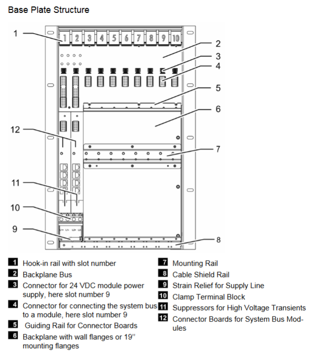
1. Base Plates
(1) Substrate type and specifications
Installation scenario of substrate model and slot number
X-BASE PLATE 10 01 10 Tablet Installation (such as installation board)
X-BASE PLATE 15 01 15 Backboard Installation
X-BASE PLAYE 15 02 15 19 inch installation
X-BASE PLATE 18 01 18 Backboard Installation
(2) Core Features
Minimum configuration: At least 1 substrate (rack ID 0), including at least 1 processor module
Scalability: Substrate 0 can expand up to 15 expansion substrates, for a total of 16 substrates
Slot allocation: 1-2 slots are reserved for the system bus module, and the remaining slots are used for other modules (subject to processor module installation restrictions)
Ventilation requirements: Blank modules should be inserted into unused slots to ensure ventilation effectiveness
2. Module types and functions
(1) Processor module
Installation restriction: Up to 4, can only be installed in slots 3-6 of rack 0 and slots 3-4 of rack 1, and some slots cannot be installed simultaneously (such as slot 5 of rack 0 and slot 4 of rack 1)
Core functions: Run user programs, perform module self testing, manage security related communication, collaborate with other processor modules to achieve redundancy
Power monitoring: Real time monitoring of 24VDC power supply voltage, voltage level can be viewed through SILworX tool
(2) I/O module
Types include: digital input/output, analog input/output, counter input module
Redundancy support: Supports 2-3 module redundancy and channel redundancy, with channels of the same number defined as redundant channels
Special function: Some modules support sequence of events (SOE) recording, and the analog input module can convert measured current to raw value (1mA corresponds to 10000) or process value (REAL type)
(3) System bus module
Functional positioning: Manage system bus A/B, slot 1 of rack 1 corresponds to system bus A, and slot 2 corresponds to system bus B
Connection requirements: When inserting one module into a single substrate, only a single bus is available. When inserting two modules, dual buses communicate simultaneously
Identification method: Identified through the System. Rack. Plot (SRS) parameter, System range 1-65535, Rack range 0-15, Slot range 1-18
(4) Communication module
Supporting protocols: SafeEthernet (safety related), Modbus, PROFIBUS and other standard protocols
Extension function: Supports ComUserTask (CUT), which can be used to write loop running programs in C language to implement custom communication protocols (non security related)
Licensing requirements: Standard agreements and CUT require long-term valid licenses, while some agreements require software activation codes
3. System bus and connections
(1) Bus characteristics
Redundant design: Dual redundant system bus (A/B), based on Ethernet technology, with electrical isolation between modules and buses, and insulation voltage of at least 1500V
Cable requirements: Copper cables should use Cat.5 (≤ 100Mbit/s) or Cat.6 (1Gbit/s) twisted pair Ethernet jumpers, support automatic crossover, and the system bus module PADT interface only supports crossover cables
Expansion capability: The maximum length of copper cable is 100m, the maximum length of fiber optic expansion is 19.6km (when processor modules are centralized), and the maximum spacing between processor modules is 1.8km when they are dispersed
(2) Substrate interconnection
Connection method: Connected through RJ-45 interface, the UP interface of the substrate is docked with the DOWN interface of the next substrate, and bus A/B cross connection is prohibited
Rack ID allocation: Based on substrate 0, the UP interface expansion substrate has odd IDs (1-15), and the DOWN interface expansion substrate has even IDs (2-14)
4. Power system
Power supply requirements: 24VDC (voltage range 19.2-30V), must comply with PELV or SELV standards, UL specifications allow maximum 150V, 10kVA adjustable power supply
Redundancy support: Can connect 2 redundant power supply units, each substrate requires fuse protection of 63A or above
Power estimation: Total power=number of processor modules x 35W+number of non processor modules x 20W+number of fans x 20W+external actuator power
Redundant configuration (improving availability)
1. Redundancy of processor modules
Configuration range: 1-4 redundant processor modules, new modules can automatically synchronize existing configurations
Fault response: When a single or multiple processor modules fail, the remaining modules maintain safe and relevant operation
Prerequisite: The user program needs to be redundantly configured, with corresponding slots reserved, and the dual system bus function is normal
2. I/O module redundancy
Module redundancy: 2-3 I/O modules of the same type are defined as redundant groups, and spare modules can be set up to avoid false alarms due to faults
Channel redundancy: Based on module redundancy, channels with the same number are automatically associated with the same global variable, and users can specify the signal synthesis method
Connector support: Redundant modules can use dedicated connector boards that occupy 2 slots, reducing on-site wiring workload
3. Redundancy of other components
System bus: Dual bus redundant operation, requiring 2 system bus modules to be inserted into each substrate
Communication redundancy: SafeEthernet supports dual physical transmission paths, and standard protocols require user program management for redundancy
Power redundancy: Dual power units are connected to L1+/L1- and L2+/L2- terminals respectively, and voltage decoupling is achieved inside the module
Programming and Configuration (Based on SILworX Tool)
1. Programming Fundamentals
Development environment: Programming through PADT (PC+SILworX), supporting IEC 61131-3 standard function blocks and custom function blocks
Program capacity: Up to 32 user programs can be loaded, with a maximum of 1023kB of program memory and 1023kB of data memory per program. The total program and data memory is 10MB (including 4kB of CRC space)
Multi tasking support: Supports 3 multitasking modes, and can set parameters such as program priority and maximum running cycle
2. Variable management
(1) Variable type
Variable type applicable scope and purpose
VAR user program, function block, function local variables, supporting CONST and RETAIN attributes
VAR-INPUT/VAR_oUTPUT All POU input/output variables
VAR_deTERNAL All POU external variables used for cross POU or global level data exchange
VAR_GLOBAL user program global variable, supporting project, configuration, and resource level definitions
VAR_TEMP All POU Temporary Variables
(2) Key configurations
Initial value: It is recommended to assign secure initial values to physical inputs and communication related variables. If not assigned, the default value is 0
System variables: pre-defined variables used to handle system properties such as temperature and power status, which can be associated and used through global variables
Mandatory function: Supports global and local variable enforcement, can set time limits, requires authorized personnel to operate, enforcement may affect security integrity
3. Program loading and updating
(1) Loading method
Download: Interrupt safety related operations, load new configuration, require controller to be in STOP state and load allowed switch to be turned on
Reload: Run without interruption, load modified configuration, require controller to be in RUN state and Reload Allow switch to be turned on, some modifications (such as communication protocol changes) do not support Reload
(2) Operating system loading
Loading order: I/O module → Communication module → System bus module → Processor module
Version management: Supports upgrading and downgrading, and can load existing versions when replacing modules to ensure compatibility
Attention: Ensure that redundant modules are running properly during loading to avoid service interruptions
User Management and Security Control
1. Project level user management (SILworX Projects)
Authorization type: Security administrators (Sec Adm) can modify user management plans and all SILworX functions; Read/write permission (R/W) can perform all functions except for user management; Read only permission (RO) can only view projects
User group characteristics: Unique name (1-31 characters), up to 100 user groups, can be assigned any number of user accounts
User account: Unique name (1-31 characters), up to 1000 accounts, can be set as the default user for the project
2. Controller level user management (Controller)
Account restriction: Up to 10 user accounts, including usernames, passwords, and access permissions. Permissions remain valid after power failure
Default Account: When no custom account is created, the default user is Administrator, without password, and has administrator privileges
Access modes: read permission (view only), read/write permission (create, load, test programs), administrator permission (load operating system, modify SRS, etc.)
3. Safety protection measures
ESD protection: Only personnel with ESD protection knowledge are allowed to modify the system or replace modules. An anti-static wristband must be worn during operation, and unused modules must be properly packaged
Mandatory restriction: The use of mandatory functions can be restricted through user profiles, resource level disabling, key switches, and other methods
Physical security: Safety shoes must be worn when installing X-BASE PLATE, and additional measures must be taken to prevent explosion risks when using in the Ex area
Diagnosis and maintenance
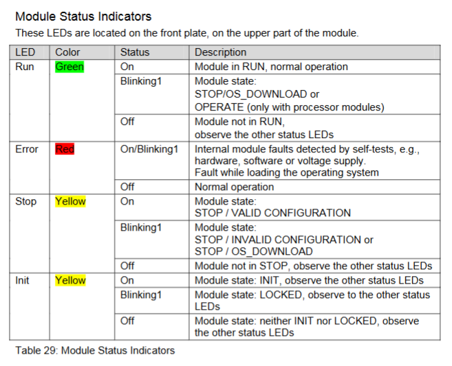
1. LED diagnostic indicator
(1) Indicator light grouping
Module status indicator lights (all modules): Run (green, running status), Error (red, fault), Stop (yellow, stop status), Init (yellow, initialization/lock status)
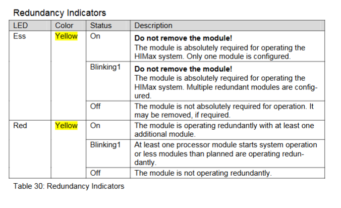
Redundancy indicator lights (processor/system bus module): Ess (yellow, module necessity indicator), Red (yellow, redundant operating status)
Fault indicator lights (processor module): System (system module fault), Field (I/O module field fault), Com (external communication fault)
(2) Definition of flicker frequency
Blinking1: Long on 600ms/Long off 600ms
Blinking2: Short on 200ms/Short off 200ms/Long on 600ms/Long off 600ms
Blinking-x: Ethernet communication synchronous flashing
2. Diagnostic history and online diagnosis
Diagnosis history: divided into short-term and long-term diagnosis. Short term diagnosis is a circular buffer, while long-term diagnosis stores user operations and configuration changes. Different modules have different storage capacities (such as X-CPU 01 supporting 2500 long-term events and 1500 short-term events)
Online diagnosis: viewed through the SILworX hardware editor online view, the faulty module is marked in red (severe fault) or yellow (minor fault), and supports viewing information such as module SRS, operating status, and consistency between configuration and actual module
3. Maintenance and Repair
Regular maintenance: Regular verification testing is required, and it is recommended to replace the fan regularly. Maintenance personnel must have professional qualifications and perform ESD protection
Fault handling: When the processor module fails, redundant modules take over control; When there is no redundancy, the controller shuts down, and the cause of the fault can be diagnosed through SILworX
Maintenance authorization: Only HIMA company has the authority to repair safety related systems and modules. Unauthorized intervention will result in the failure of safety functions and warranty
Lifecycle Management
1. Installation phase
Environmental requirements: working temperature 0-60 ℃, storage temperature -40-85 ℃, altitude<2000m, protection level IP20 (special scenarios require an IP54 or higher enclosure)
Wiring specifications: Supports 4 types of wiring schemes (single/redundant connector board+direct/FTAs connection), cables must be kept away from electromagnetic interference sources, and grounding must comply with SELV/PELV requirements
Heat dissipation considerations: A heat dissipation structure should be designed for a closed environment, and the effective heat dissipation area should be calculated based on the installation type to ensure that the operating temperature of the module does not exceed 60 ℃
2. Startup phase
(1) Control cabinet startup
Preprocessing: Test all input and output terminals for abnormal external voltage (such as 230V), check cable insulation resistance and grounding faults
Power supply inspection: Confirm that the polarity of the 24VDC power supply is correct, the voltage is stable, and the ripple meets the requirements
(2) PES startup
Startup steps: Set the system bus module IP and SRS → Specify the "responsible" system bus module → Configure the processor module → Interconnect the substrate → Log in to the system → Load the project → Start the system
Rack ID allocation: Modify through the system bus module to ensure that all modules on the substrate are in STOP state and the new ID configuration is consistent
3. Operation and shutdown
Operation monitoring: View system status, event records, and fault information through SILworX, and regularly backup project configurations
Shutdown disposal: Follow the requirements of the component manual for retirement and disposal to ensure electrical safety
Supplementary model
1、 Base Plates model
X-BASE PLATE 10 01 (10 slots, flat panel installation)
X-BASE PLATE 15 01 (15 slots, backplate installation)
X-BASE PLATE 15 02 (15 slots, 19 inch installation)
X-BASE PLATE 18 01 (18 slots, backplate installation)
2、 Module model
(1) Processor module
X-CPU 01
(2) System bus module
X-SB 01
(3) Communication module
X-COM 01
(4) I/O module
Analog input module
X-AI 32 01 (32 channels)
X-AI 32 02 SOE (32 channels, supporting event sequence recording)
Analog output module
X-AO 16 01 (16 channels)
Counter input module
X-CI 24 01 (24 channels)
Digital input module
X-DI 16 01 (16 channels)
X-DI 32 01 (32 channels)
X-DI 32 02 (32 channels, suitable for proximity switches)
X-DI 32 03 (32 channels)
X-DI 32 04 SOE (32 channels, supporting event sequence recording)
X-DI 32 05 SOE (32 channels, suitable for proximity switches, supports event sequence recording)
X-DI 64 01 (64 channels)
Digital output module
X-DO 12 01 (12 channels, relay output)
X-DO 12 02 (12 channels)
X-DO 24 01 (24 channels)
X-DO 24 02 (24 channels)
X-DO 32 01 (32 channels)
(5) Fan module
X-FAN (specific model not subdivided, refer to manual HI 801 033)
3、 Connector Board Model
X-CB 008 01 (single connector board with screw terminals)
X-CB 008 02 (redundant connector board with screw terminals)
X-CB 008 03 (single connector board with cable plug)
X-CB 008 04 (redundant connector board with cable plug)
4、 Field Terminal Component (FTA) Model
X-FTA AI 32 01 01
X-FTA DI 32 01 01
X-FTA DI 32 02 01
X-FTA DO 12 01 01
X-FTA DO 24 01 01
X-FTA 001 01
X-FTA 001 02
X-FTA 002 01
X-FTA 003 02
X-FTA 005 02
X-FTA 006 01
X-FTA 006 02
X-FTA 007 02
X-FTA 008 02
X-FTA 009 02
5、 Other related models
H 7201 (involving terminal XG13, refer to the content related to screw locking torque)
X-DI6451
X-DI3202
X-DO3251
- OMRON
- ABB
- General Electric
- EMERSON
- Honeywell
- HIMA
- ALSTOM
- Rolls-Royce
- MOTOROLA
- Rockwell
- Siemens
- Woodward
- YOKOGAWA
- FOXBORO
- KOLLMORGEN
- MOOG
- KB
- YAMAHA
- BENDER
- TEKTRONIX
- Westinghouse
- AMAT
- AB
- XYCOM
- Yaskawa
- B&R
- Schneider
- KONGSBERG
- NI
- WATLOW
- ProSoft
- SEW
- ADVANCED
- Reliance
- TRICONEX
- METSO
- MAN
- Advantest
- STUDER
- DANAHER MOTION
- Bently
- Galil
- EATON
- MOLEX
- DEIF
- B&W
- ZYGO
- Aerotech
- DANFOSS
- Beijer
- Moxa
- Rexroth
- Johnson
- WAGO
- TOSHIBA
- BMCM
- SMC
- HITACHI
- HIRSCHMANN
- Application field
- XP POWER
- CTI
- TRICON
- STOBER
- Thinklogical
- Horner Automation
- Meggitt
- Fanuc
- Baldor
- SHINKAWA
- Other Brands
- UniOP
- KUKA
- Iba
- Beckhoff
-
 Basler XR2002F Voltage Regulator 9139400101
 -
 Basler 2D80367G23 DXCB De-Excitation Module 1200V 5000A
 -
 Basler SR4A-2B15B3A Static Regulator 120V 50/60Hz
 -
 Basler SSR 125-12NF Static Regulator 9 1859 00 106
 -
 Basler BE1-BPR Breaker Protection Relay 9272000315
 -
 Basler SSR 63-12 Static Regulator 9 1859 00 101
 -
 Basler AEM-2020 Analog Expansion Module
 -
 Basler BE 25231-001 Transformer BE25231001
 -
 Basler MVC 108 Manual Voltage Control 9037000102
 -
 Basler PSS-100-Y5 Power System Stabilizer 0.1-5.0Hz
 -
 Basler Electric BE1A-25-M1G-A6T-N4V1F Sync-Check Relay
 -
 Basler Electric SR8A2B10B1A Static Voltage Regulator
 -
Basler Electric SR8A2B10B1A Static Voltage Regulator
-
Basler Electric SSR 125-12 Static Voltage Regulator 9185900102
-
 Basler Electric 90-73900-102 Power Supply (Westinghouse 2374A07G03)
 -
 Basler Electric 9400200117 Control Power Unit 12/24VDC 20W
 -
Basler Electric BE1-87G Solid State Generator Differential Relay
-
 Basler Electric BE1-32R Style C3ED1TA0S1F Solid State Protective Relay
 -
Basler Electric SR32A2B05B3E Static Voltage Regulator
-
 Basler Electric SR8A2B06B3A Static Voltage Regulator
 -
Basler MOC3502 90-72300-116 Motor Potentiometer
-
 Basler SR4A2310B1A Static Voltage Regulator
 -
 Basler Electric 90-88800-102 PRS-250 Veri-Sync Relay
 -
Basler Electric 90-88800-102 PRS-250 Veri-Sync Relay
-
Basler SR4A-2B05A3E Static Regulator SR4A2B05A3E
-
 Basler 9-0723-00-130 9072300130 Control Module
 -
 Basler BE1-79MA10A6JC0L0F Reclosing Relay
 -
 Basler CBS-377 Current Boost System 91096001
 -
Basler SR4A1B05A3A Static Regulator 480V 62.5V 10VA
-
 Basler BE159N A7ED1JC0S0F Protective Relay BE159N-0
 -
 Basler BE3-25A Auto-Synchronizer S.No. 728
 -
 Basler BE1-50 Instantaneous Overcurrent Relay G4EA1RG0N0F
 -
 Basler Electric KT3B Voltage Regulator
 -
 Basler Electric ACA2500-14GCSYM GigE Camera
 -
 Basler Electric XR2002F Voltage Regulator
 -
 Basler Electric BE1-50 Instantaneous Overcurrent Relay F2EA1PA0N5F
 -
 Basler Electric CBS 212A Current Boost System
 -
Basler Electric BE147NE3FE1PC3N3F Negative Sequence Voltage Relay
-
 Basler Electric BE1-79MA10A6JC0L0F Automatic Reclosing Relay
 -
Basler Electric BE1-59N A6E E1C B0N1F Neutral Overvoltage Relay
-
 Basler Electric MVC 108 Manual Voltage Control
 -
 Basler Electric BE1-59-A4E-E1C-A0N0F Overvoltage Relay
 -
Basler BE1-57/27R Solid State Protective Relay
-
 Basler BE3-25AX Time Overcurrent Relay
 -
BASLER ELECTRIC BE1-24/A1EF1JC1N0F / BE124A1EF1JC1N0F Overvoltage Relay
-
Basler Electric Solid State Protective Relay BE1-32R Style B2ED1PB0N0F
-
Basler BE3-51-3E1E1 9320000110 24VDC Overcurrent Relay
-
 Basler UFOV 260A Underfrequency Overvoltage Module
 -
 Basler 50F4EA1PA0N0F Instantaneous Overcurrent Relay
 -
Basler BE1-50 Instantaneous Overcurrent Relay
-
 Basler BE1-32 Solid State Protective Relay
 -
Basler SCP 250-G-60 VAR Power Factor Controller
-
Basler BE1-59N A5EE1KC0N0F Ground Fault Relay
-
Basler BE1-79A Reclosing Relay
-
Basler BE1-32R E1EA1OA0N0F Reverse Power Relay
-
 Basler DCQA-103 DCQC104-1 CMX-7D Circuit Board
 -
 Basler SSR125-12 Static Regulator 918500102
 -
Basler 90 17709 112 Regulator Control Board
-
 Basler AVC63-4 AVC634 Voltage Regulator
 -
 Basler 9 1049 04 100 PC Board Control Module
 -
Basler SR4A-2B03B3A Static Voltage Regulator
-
 Basler SR8A-2B15B3A Static Voltage Regulator
 -
 Basler KR7FFX Static Regulator 840V
 -
 Basler EL200-7 Voltage Regulator 90-660VAC 7A
 -
 Basler PRP210-1 Reverse Power Relay 9056300102
 -
 Basler SSR 63-12 Static Regulator 600VAC
 -
 Basler 9289901106 Digital Board
 -
Basler DECS100 Voltage Regulator DECS100A01
-
Basler Electric CEM-2020 Contact Expansion Module
-
Basler Electric BE3-25-1 C1 N4 Synchronizing Check Relay
-
Basler Electric ACA2000-50GM GigE Camera 2MP 50fps
-
 Basler Electric ACA2240-20GMSYM GigE Camera Sony IMX264
 -
Basler BE1-50G Ground Overcurrent Relay
-
Basler PRS250 Veri-Sync Relay
-
Basler MOC2199 Output Module
-
 Basler UFOV 260A Underfrequency Overvoltage Module
 -
 Basler BE-15482-001 Control Module
 -
Basler LSP4-7 Protective Relay
-
 Basler SCP 250-G-60 VAR Power Factor Controller
 -
Basler BE146N Negative Sequence Overcurrent Relay
-
Basler APR63-5 Automatic Voltage Regulator
-
Basler 9507900107 SR8A Retrofit Voltage Regulator
-
Basler BE1-320 Directional Power Relay
-
 Basler KR7F Voltage Regulator 9116200100
 -
Basler UFOV 260A Overvoltage Protective Module
-
 Basler AEC63-7 Analog Excitation Controller
 -
Basler 9992D90G01 Control Module
-
Basler 6966D22G01 Control Board
-
Basler 6965D40G01 Control Board
-
 Basler BE1-50/51M-104 Overcurrent Relay
 -
Basler BE1-BPR Programmable Breaker Relay
-
 BASLER Electric SSR 125-9 1256 00 102 Static Voltage Regulator
 -
Basler Electric MVC 112 Manual Voltage Control
-
 Basler Electric 9321000102 Control Module
 -
 Basler Electric RA-70-MDCT7 Rectifier Assembly
 -
 Basler Electric ACA1300-60GM GigE Camera
 -
 Basler Electric 6427C85G01 Interface Board
 -
Basler Electric 6965D05G01 Control Board
-
Basler Electric ACA2500-14UC Current Transducer
-
Basler Electric 9170206111 Protective Relay
-
Basler Electric BE1-11-G6D1M1J1P0E000 Protection Relay
-
Basler Electric BE1-50/51B-107 Overcurrent Relay
-
 Basler 9121000106 Voltage Controller
 -
 Basler B3E-E1P-A0N0F Solid State Protective Relay
 -
 Basler 9121000106 Manual Voltage Control
 -
Basler PRP320 Motor Pull-out Relay
-
 Basler SSE-N 250-9KW Shunt Exciter Regulator
 -
 Basler BE1-50-51B-107 Overcurrent Relay
 -
 BASLER ELECTRIC MVC 108 MANUAL VOLTAGE CONTROL MODULE 9 0370 00 102
 -
Basler BE1-59N-A7E-D1J-D0N0F Ground Overvoltage Relay
-
Basler BE1-46N-G1E-B8P-B0N0F Negative Sequence Overcurrent Relay
-
Basler BE1-951 Overcurrent Protection System
-
 Basler Electric MOC2199 Motor Operated Potentiometer
 -
Basler Electric BE1-60 Voltage Balance Solid State Relay B1FA1C1M1F
-
Basler Electric BE1-67N Directional Overcurrent Relay
-
Basler Electric PIA2400-17GM Interface Module
-
 Basler Electric V6RAB Rectifier Module
 -
Basler Electric BE1-32R Reverse Power Relay B2E E1R A0N1F
-
Basler Electric IFM-150 Firing Circuit Chassis 120V AC
-
 Basler Electric IFM-102 Firing Circuit Chassis 120V AC
 -
 Basler Electric 9170206111 NSNP Control Module
 -
Basler Electric SSR 63-12 Static Voltage Regulator
-
 Basler UFOV 260A Overvoltage Protective Module
 -
Basler SCA1300-32GM CCD Camera Lens Enclosure
-
Basler BA1-27 Under Voltage Relay
-
Basler 149D866G06 Control Board
-
 Basler 9072300130 Power Supply Module
 -
Basler CBS 305 Current Boost System


