
YASKAWA AC Servo Drive HR Series (CACR-HR) Multi functional/Positioning Control
Grounding requirements:
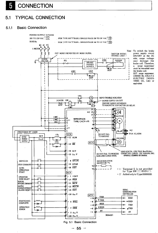
Driver FG terminal → grounding electrode (Class 3 grounding, resistance ≤ 100 Ω);
Motor frame ground → driver FG terminal to avoid common ground interference.
Noise control:
Install a noise filter on the power side (such as HR03BAB with LF-205A);
The distance between power lines and signal lines should be ≥ 30cm, and wiring in the same conduit is prohibited.
Functional operations (I/O, communication, parameters)
1. I/O signal operation
Input signal timing: SVON, AST and other signals need to maintain a stable level of ≥ 5ms to avoid false triggering;
Output signal status:
POS1 (positioning completed): ON when the deviation between the current position and the target position is ≤ P6 (positioning completed width, 1-250 units);
NEAR (positioning proximity): ON when the deviation is ≤ P45 (positioning proximity width, 0-3000 units).
2. Serial communication (RS422)
Communication specifications:
Baud rate: 9600/4800/2400/1200Baud (default 9600);
Data format: 1 start bit+7 data bits+1 even check bit+1 stop bit.
Core command:
SVON: Servo Enable;
MOV ± nnnnnn: Absolute positioning (± 8-bit position data);
ZRN: Start back to zero;
PRMpp=± nnnnnnnn: Set parameters (pp=parameter number).
Multi axis control: Supports 16 axes and specifies the control object through axis addresses (1-16).
3. Parameter Setting (Example of Core Parameters)
Parameter Number, Parameter Name, Unit Range, Function Description
P1 position loop gain Kp s ⁻¹ 0-200 adjusts position control response speed, the larger the value, the faster the response (prone to oscillation)
P2 speed loop gain Kv × 2.5Hz 1-200 adjustment speed control response speed, matching system rigidity
P4 1st feed rate x 1000 units/minute 1-240000 reference speed in automatic/manual mode
When the deviation of the width unit 1-250 after P6 positioning is ≤ this value, the POS1 signal is ON
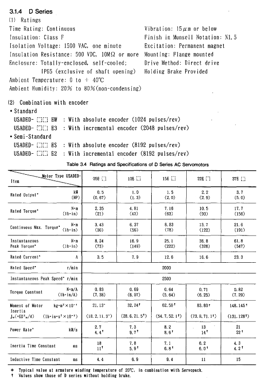
P7 motor selection -0-79 matching motor model (e.g. 32=USAREM-A5CS)
P8 encoder pulse P/R (× 4) 4096-32768 encoder pulse per revolution (absolute 8192P/R set to 32768)
Display/Monitoring and Maintenance
1. Display function
LED indicator light:
MAIN (red): residual voltage in the main circuit (slowly extinguishes after power failure);
RUN (green): Control power supply is normal (+5V normal);
ALM (red): Fault alarm (check the 7-segment digital tube code when it lights up).
7-segment digital tube:
Normal state: Display current position (PUN) and speed (NFB);
Fault status: Display code (such as OC=overcurrent, OL=overload, BAT=low battery).
2. Trial operation process
Preparation stage:
Check the wiring (main circuit/control circuit is not loose) and parameters (P7/P8/P9 matching motor and encoder);
Absolute encoder reset: Short circuit the specific pin of the encoder and release it after powering on for ≥ 2 minutes.
Test operation:
Servo Enable: Send SVON command, confirm that RUN light is on and ALM light is off;
Jogging test: Send JOG+1000 command (1000 units/minute) to confirm that the motor rotates smoothly;
Positioning test: Send MOV+10000 command and confirm that POS1 signal is ON after positioning is completed.
3. Maintenance and troubleshooting
Battery replacement: Replace the absolute encoder battery (3.6V) when the voltage is ≤ 3.3V, and replace it after power failure (to avoid data loss).
Common troubleshooting:
|Alarm code | Fault cause | Handling measures|
|OC (overcurrent) | Main circuit overcurrent (≥ 1.2 times peak current) | Check if the motor wiring and load are stuck|
|OL (overload) | Motor overload (exceeding allowable load inertia) | Reduce load inertia and acceleration rate|
|PG (Encoder Disconnected) | Encoder Cable Loose/Disconnected | Check 3CN Wiring and Encoder for Damage|
|BAT (low battery) | Absolute encoder battery voltage low | Replace 3.6V lithium battery (such as CR2450)|
Installation and environmental requirements
Motor installation:
Installation method: Both horizontal and vertical can be used, with axis centering deviation ≤ 0.03mm;
Axial load: The radial/axial load shall not exceed the specifications in Table 3.9 (such as M series 03B model radial 490N).
Driver installation:
Rack mounted (BAB): vertically installed, with a spacing of ≥ 10cm (for heat dissipation);
Base type (BB): vertically installed, avoiding direct sunlight/condensation environment.
Environmental restrictions:
Temperature: driver 0-55 ℃, motor 0-40 ℃;
Humidity: 20% -80% RH (without condensation);
Dust: Do not use in dusty or corrosive gas environments.
- OMRON
- ABB
- General Electric
- EMERSON
- Honeywell
- HIMA
- ALSTOM
- Rolls-Royce
- MOTOROLA
- Rockwell
- Siemens
- Woodward
- YOKOGAWA
- FOXBORO
- KOLLMORGEN
- MOOG
- KB
- YAMAHA
- BENDER
- TEKTRONIX
- Westinghouse
- AMAT
- AB
- XYCOM
- Yaskawa
- B&R
- Schneider
- KONGSBERG
- NI
- WATLOW
- ProSoft
- SEW
- ADVANCED
- Reliance
- TRICONEX
- METSO
- MAN
- Advantest
- STUDER
- DANAHER MOTION
- Bently
- Galil
- EATON
- MOLEX
- DEIF
- B&W
- ZYGO
- Aerotech
- DANFOSS
- Beijer
- Moxa
- Rexroth
- Johnson
- WAGO
- TOSHIBA
- BMCM
- SMC
- HITACHI
- HIRSCHMANN
- Application field
- XP POWER
- CTI
- TRICON
- STOBER
- Thinklogical
- Horner Automation
- Meggitt
- Fanuc
- Baldor
- SHINKAWA
- Other Brands
- UniOP
- KUKA
- Iba
- Beckhoff
-
 Basler D90 96801 100 PCB Card
 -
 Basler XR2002F Voltage Regulator (110 VAC, 48-480 Hz)
 -
 Basler SR8A-2B14B3A Regulator
 -
 Basler 9561500100 Module
 -
 Basler DECS-400 BE1-11 System
 -
 Basler DECS-100-B15 Excitation Control
 -
 Basler SCP 210 Frequency Controller
 -
 Basler SR4A-2B15B3A Static Voltage Regulator
 -
 Basler BE1-32R Power Relay
 -
 Basler PIA2400-17GM Power Interface Adapter
 -
 Basler MVC 232 Manual Voltage Control Module
 -
 Basler SSR 32-12 Static Voltage Regulator
 -
 Basler 5MW AVR Generator Voltage Regulator
 -
 Basler VR63-4B Voltage Regulator
 -
 Basler DECS-100-A05 AVR for Engine Generator
 -
 Basler DECS-100-B15 Automatic Voltage Regulator
 -
 Basler BE1-32R Directional Power Relay
 -
 Basler BE1-87B Differential Relay
 -
 Basler UFOV 260A Protective Module
 -
 Basler 9-2614-02-100 PCB Rev M
 -
Basler DECS-100-B15 Digital AVR
-
 Basler 9284900103 PS DECS-400N
 -
 Basler D4N3H1U Intertie Protection
 -
 Basler DECS-100-B15 A15 AVR
 -
 Basler KR4F Voltage Regulator
 -
 Basler BE26434 T14 Transformer
 -
 Basler SR8A-2B15B3A Regulator
 -
 Westinghouse 774B472A12 AR Relay
 -
Basler DECS-100-B15 AVR
-
Basler XR2002F Regulator 110V
-
Basler SR125-E Static Regulator
-
 Basler SSR 125-12 Regulator
 -
 Basler MOC2599 Motor Pot
 -
 Basler BE1-DFPR Feeder Relay
 -
 Basler CBS 305 Current Boost
 -
 Basler BE1-25 AutoSync
 -
 Basler MVC 300 Voltage Control
 -
 Basler BE3-25A AutoSync
 -
 Basler KR7FF Static Regulator
 -
 Basler 90-49000-100 Regulator
 -
 Basler 880 kVA Dry Type Transformer Specs
 -
 Basler Electric BE1-25 Sync-Check Relay Specs
 -
 Basler SSR 125-12 Voltage Regulator Specs
 -
 Basler Electric BE1-851 Overcurrent Relay Review
 -
Basler Electric 149D930G02 Control Sub-Assembly
-
 Basler Electric BE1-81O/UT Frequency Relay Specs
 -
 Basler Electric BE1-51/27C Overcurrent Relay
 -
 Basler Electric 149D956G02 Industrial Component
 -
Basler Electric BE1-51A Overcurrent Relay Specs
-
 Basler Electric BE1-40Q Loss of Excitation Relay
 -
 Basler DECS-200 Excitation Control System
 -
 Basler DECS-200 Voltage Regulator 56-277V AC / 125V DC
 -
Basler BE1-87T Transformer Differential Relay
-
 Basler RDP-110-S1 Protection Relay
 -
 Basler BE1-700V Digital Protective Relay
 -
 Basler BE1-951 Overcurrent Protection System
 -
 Basler DECS-300 Digital Excitation Control
 -
 Basler DECS-200 Digital Excitation Control
 -
 Basler DECS-200-1C Excitation Control System
 -
Basler DECS-200-1L Digital Excitation Control
-
 Basler Electric BE1-GPS Generator Protection System
 -
Basler Electric DECS-200-1C Digital Excitation Controller
-
 Basler Electric DECS125-15 Excitation Control with Power Module
 -
 Basler Electric BE1-87G Differential Relay
 -
 Basler Electric BE1-11 Protection System I5A3M2P2N0EA00
 -
Basler Electric DECS-200-1C Excitation Control System
-
Basler Electric BE1-11g Generator Protection Relay
-
Basler Electric DECS 125-15-B2C1 V2.0.9 Excitation Control
-
 Basler Electric BE1-81O/UT3ED1JA7N2F Frequency Relay
 -
Basler Electric BE1-81O/UT3EE1YB7N1F Frequency Relay
-
 Basler Electric DECS-200-1L Digital Excitation Control System
 -
Basler DECS125-15-B2C1 Excitation Control
-
 Basler 9507900205 SSR Retrofit Voltage Regulator
 -
 Basler BE2000E Digital Voltage Regulator
 -
 Basler BE1-GPS Generator Protection System
 -
Basler DECS-250-CN1CN1N Digital Excitation Control
-
 Basler DGC-2020 Genset Controller
 -
 Basler BE1-81O UT3ED1LA7N0F Frequency Relay (Variant)
 -
 Basler BE1-81O UT3EE1YA9S0F Frequency Relay (Variant)
 -
Basler BE1-81O Over/Under Frequency Relay
-
Basler DECS125-15 Digital Excitation Control
-
Basler Electric BE1-951 Overcurrent Protection System
-
 Basler Electric BE1-700V Digital Protective Relay
 -
 Basler Electric APR63-5 Automatic Voltage Regulator
 -
Basler Electric BE1-851 Overcurrent Protection System
-
Basler Electric DECS-250-LN1SN1N Excitation Control
-
 Basler Electric BE1-87T Transformer Differential Relay
 -
Basler Electric DECS-200-1L Excitation Control System
-
 Basler Electric 9310300100 DECS-300 Excitation Control
 -
 Basler Electric SSE-N 125-4.5KW Shunt Exciter Regulator
 -
 Basler Electric DGC-2020HD-5NS1DNSBA Genset Controller
 -
Basler Electric BE1-81-O/UT3EE1JB7N1F Frequency Relay
-
Basler Electric BE1-81T1EE1WA0N1F Frequency Relay
-
 Basler Electric BE1-25M1EA6PN5R1F Sync-Check Relay
 -
 Basler Electric BE1-GPS Generator Protection System
 -
Basler Electric DECS-250-LN1SN1N Excitation Control Rev V
-
 Basler Electric DECS-250-CN2CN1N Excitation Control
 -
Basler Electric BE1-50/51B-207 Overcurrent Relay
-
Basler Electric DECS-300-C0N0 Excitation Control System
-
Basler Electric DECS-200 Digital Excitation Control System
-
Basler Electric DECS-250-LN1CN1N Excitation Unit
-
Basler Electric DECS-250 LN2SA1D Excitation Unit Specs
-
Basler Electric BE1-87T Transformer Relay Review
-
Basler Electric BE1-11 Protection System
-
Basler Electric BE1-GPS100-E4N1H1N Protection System
-
 Allen-Bradley 442G-MABH-R Safety Module
 -
 Beckhoff CX1030-0111 PLC Assembly Profile
 -
 FANUC IC693CPU364 PLC Module
 -
 Orange Denmark Type 200816 220 PLC Specs
 -
 OMRON C200H-SNT31 Sysmac PLC Module
 -
 Allen Bradley 20AB022A3AYNANC0 PowerFlex 70
 -
 OMRON C200HW-PCU01 Position Control Unit
 -
 ABB AO845A-eA Analog Output Module
 -
 OMRON CJ1M-CPU22 CPU Unit
 -
 Allen Bradley 100-E265ED11 Contactor
 -
 Honeywell 51304511-100 Interface Module
 -
 SOLEXY BXF3S0101N0018 Gateway Module
 -
 OMRON CJ2H-CPU65 CPU Unit
 -
 Automation Direct GS2-45P0 AC Drive
 -
 M68-2000 2-Axis Motion CNC Controller
 -
 OMRON CJ1M-CPU11 V3.0 PLC CPU Unit
 -
 OMRON CJ1W-NC413 4-Axis Positioning Controller
 -
 OMRON 3G2A3-PRO16 Programming Console HMI
 -
 Siemens 3VT8440-2AA04-2GA2 Molded Case Circuit Breaker
 -
 Siemens 3RT5045 Contactor Series
 -
 OMRON C200HS-CPU01-E SYSMAC PLC Controller
 -
 OMRON C500-NC103-E Positioning Control Unit
 -
 OMRON CJ1W-TC001 Temperature Control Unit


