
YASKAWA MP2000 series machine controller communication module
YASKAWA MP2000 series machine controller communication module
The entire process of starting the communication module
Step 1: Prepare using the machine
Essential equipment: MP2000 series controller, communication module, communication partner device, dedicated cable, computer with MPE720 installed
Controller compatibility: MP2200 (JEPMC-BU2200/BU2210, maximum of 8 modules), MP2300 (JEPMC-MP2300, maximum of 3 modules), MP210M (JAPMC-MC2140, expansion board required, maximum of 8 modules), MP2500MD (JEPMC-MP2540-D , expansion board required, maximum of 8 modules)
Step 2: Module installation and disassembly
Installation steps: Power off → Remove the machine controller battery cover → Remove the optional module cover → Align the guide rail and insert the module → Install the cover → Power on
Disassembly steps: Power off → Backup program → Remove cable → Remove battery cover → Remove cover → Use battery cover protrusion to pry module → Pull out module
Step 3: Communication Manager Settings
Supported port types: Serial (RS-232C), Ethernet, Ethernet (LP), CP-215
Key setting example (Ethernet): Set the computer IP to 192.168.1.2 and subnet mask to 255.255.255.0; Set the Logical PT to Ethernet and fill in the computer IP address for the Communication Manager
Step 4: Automatic Configuration Execution
Trigger method: Set "CNFG" to ON and restart MP2200/MP2300; MP210M/MP2500MD operated through the MPE720 menu
Result difference:
CNFG Initiate Results
The ON module has been updated, and all communication modules are configured according to default settings
The ON/OFF module has been updated, with existing modules retaining their configuration and new modules using default settings
Step 5: MPE720 Startup and Transfer Definition
Ver.6: Online → Communications Setting → Select Logical Port → Set Parameters
Ver.5.xx: Start MPE720 → Open PLC folder → Properties → Network → Check OnLine → Select logical port
Transfer definition: Open the module composition definition screen → double-click the corresponding module → set parameters → save to flash memory

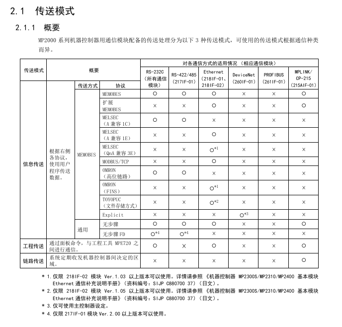
Detailed explanation of transmission mode and protocol
Classification of transmission modes
Mode applicable communication mode (module) core characteristics
Information transmission RS-232C (all), Ethernet (218IF-01/02), MPLINK (215AIF-01) event triggered, using MSG-SND/MSG-RCV functions
Engineering transmission RS-232C (all), Ethernet (218IF-01/02), MPLINK (215AIF-01) panel commands+MPE720 for program transmission
Link Transport MPLINK (215AIF-01) regularly sends and receives, only supported by 215AIF-01
Core Communication Protocol
MEMOBU: Yaskawa standard, main controller specifies sub controller address communication, function codes include 01H (read winding), 03H (read hold register), etc., supporting 1-2000 bits (bit data), 1-125 words (word data)
Extended MEMOBU: MEMOBU extension, adding function codes such as 09H (extended read hold register), transmitting 1-508 words at once, supporting MEMOBU/general information mode
MELSEC: Compatible with Mitsubishi A-series, supports communication between CPUs and fixed buffer communication, with function codes corresponding to ACPU universal commands (such as WR → 01H/02H)
MODBUS/TCP: Industrial Ethernet protocol, supports 1-2000 bits (read winding), 1-125 words (read register), 218IF-01/02 automatic conversion protocol
No steps: Directly transfer data from the M register, divided into word (1-254 words) and byte (1-508 bytes) units, with no response
Serial communication (taking 217IF-01 as an example)
Ports and protocols
Interface: RS-232C (PORT, 9-pin), RS-422/485 (14 pin)
Supporting protocols: MEMOBU, MELSEC, OMRON, Stepless, Stepless FD (Full Duplex, Maximum Received 5080 Words)
Transmission definition parameters
Example of Parameter Setting Content
Transmission Protocol MEMOBU/MELSEC/OMRON/Stepless MEMOBU
Master (Address 0)/Slave (Address 1~63) Slave, Address 1
Baud rate 9600/19200bps 19200bps
Data length 7/8 bits 8 bits
Parity Even/Odd/None Even
Connection Example
Connected to MELSEC: RS-232C (pin 2=TXD, 3=RXD) of 217IF-01 connected to Mitsubishi AJ71UC24 (pin 2=RXD, 3=TXD), MELSEC set station number 01, baud rate 19200bps
Connected to frequency converter: RS-485 (pin 3=RX+, 4=RX -, 8=TX+, 9=TX -) of 217IF-01 is connected to VS-616G5, and frequency converter H5-01=1 (address) H5-02=9600bps
Key module characteristics (218IF-01/02, 260IF-01)
218IF-01 module
Interface: RS-232C (PORT), Ethernet (10Base-T, RJ45)
Specification: Ethernet transmission speed of 10Mbps, half duplex; RS-232C maximum transmission 15m
Ethernet settings: IP address (default 192.168.1.1), subnet mask, connection parameters (TCP/UDP, ports 256~65535)
218IF-02 module
Interface: RS-232C (PORT), Ethernet (100Base TX/10Base-T)
Advantages: Supports Ethernet (LP) ports, higher engineering communication speed, maximum transmission of 100m (100Base TX)
260IF-01 module
Communication: DeviceNet, supports Explicit protocol, main controller settings
Specification: Maximum number of nodes 64, transmission speed 125/250/500kbps
Key issues
Question 1: There are two triggering methods for the automatic configuration of MP2000 series communication modules. Which controllers are they applicable to? What are the differences in configuration results?
- OMRON
- ABB
- General Electric
- EMERSON
- Honeywell
- HIMA
- ALSTOM
- Rolls-Royce
- MOTOROLA
- Rockwell
- Siemens
- Woodward
- YOKOGAWA
- FOXBORO
- KOLLMORGEN
- MOOG
- KB
- YAMAHA
- BENDER
- TEKTRONIX
- Westinghouse
- AMAT
- AB
- XYCOM
- Yaskawa
- B&R
- Schneider
- KONGSBERG
- NI
- WATLOW
- ProSoft
- SEW
- ADVANCED
- Reliance
- TRICONEX
- METSO
- MAN
- Advantest
- STUDER
- DANAHER MOTION
- Bently
- Galil
- EATON
- MOLEX
- DEIF
- B&W
- ZYGO
- Aerotech
- DANFOSS
- Beijer
- Moxa
- Rexroth
- Johnson
- WAGO
- TOSHIBA
- BMCM
- SMC
- HITACHI
- HIRSCHMANN
- Application field
- XP POWER
- CTI
- TRICON
- STOBER
- Thinklogical
- Horner Automation
- Meggitt
- Fanuc
- Baldor
- SHINKAWA
- Other Brands
- UniOP
- KUKA
- Iba
- Beckhoff
-
 Basler D90 96801 100 PCB Card
 -
 Basler XR2002F Voltage Regulator (110 VAC, 48-480 Hz)
 -
 Basler SR8A-2B14B3A Regulator
 -
 Basler 9561500100 Module
 -
 Basler DECS-400 BE1-11 System
 -
 Basler DECS-100-B15 Excitation Control
 -
 Basler SCP 210 Frequency Controller
 -
 Basler SR4A-2B15B3A Static Voltage Regulator
 -
 Basler BE1-32R Power Relay
 -
 Basler PIA2400-17GM Power Interface Adapter
 -
 Basler MVC 232 Manual Voltage Control Module
 -
 Basler SSR 32-12 Static Voltage Regulator
 -
 Basler 5MW AVR Generator Voltage Regulator
 -
 Basler VR63-4B Voltage Regulator
 -
 Basler DECS-100-A05 AVR for Engine Generator
 -
 Basler DECS-100-B15 Automatic Voltage Regulator
 -
 Basler BE1-32R Directional Power Relay
 -
 Basler BE1-87B Differential Relay
 -
 Basler UFOV 260A Protective Module
 -
 Basler 9-2614-02-100 PCB Rev M
 -
Basler DECS-100-B15 Digital AVR
-
 Basler 9284900103 PS DECS-400N
 -
 Basler D4N3H1U Intertie Protection
 -
 Basler DECS-100-B15 A15 AVR
 -
 Basler KR4F Voltage Regulator
 -
 Basler BE26434 T14 Transformer
 -
 Basler SR8A-2B15B3A Regulator
 -
 Westinghouse 774B472A12 AR Relay
 -
Basler DECS-100-B15 AVR
-
Basler XR2002F Regulator 110V
-
Basler SR125-E Static Regulator
-
 Basler SSR 125-12 Regulator
 -
 Basler MOC2599 Motor Pot
 -
 Basler BE1-DFPR Feeder Relay
 -
 Basler CBS 305 Current Boost
 -
 Basler BE1-25 AutoSync
 -
 Basler MVC 300 Voltage Control
 -
 Basler BE3-25A AutoSync
 -
 Basler KR7FF Static Regulator
 -
 Basler 90-49000-100 Regulator
 -
 Basler 880 kVA Dry Type Transformer Specs
 -
 Basler Electric BE1-25 Sync-Check Relay Specs
 -
 Basler SSR 125-12 Voltage Regulator Specs
 -
 Basler Electric BE1-851 Overcurrent Relay Review
 -
Basler Electric 149D930G02 Control Sub-Assembly
-
 Basler Electric BE1-81O/UT Frequency Relay Specs
 -
 Basler Electric BE1-51/27C Overcurrent Relay
 -
 Basler Electric 149D956G02 Industrial Component
 -
Basler Electric BE1-51A Overcurrent Relay Specs
-
 Basler Electric BE1-40Q Loss of Excitation Relay
 -
 Basler DECS-200 Excitation Control System
 -
 Basler DECS-200 Voltage Regulator 56-277V AC / 125V DC
 -
Basler BE1-87T Transformer Differential Relay
-
 Basler RDP-110-S1 Protection Relay
 -
 Basler BE1-700V Digital Protective Relay
 -
 Basler BE1-951 Overcurrent Protection System
 -
 Basler DECS-300 Digital Excitation Control
 -
 Basler DECS-200 Digital Excitation Control
 -
 Basler DECS-200-1C Excitation Control System
 -
Basler DECS-200-1L Digital Excitation Control
-
 Basler Electric BE1-GPS Generator Protection System
 -
Basler Electric DECS-200-1C Digital Excitation Controller
-
 Basler Electric DECS125-15 Excitation Control with Power Module
 -
 Basler Electric BE1-87G Differential Relay
 -
 Basler Electric BE1-11 Protection System I5A3M2P2N0EA00
 -
Basler Electric DECS-200-1C Excitation Control System
-
Basler Electric BE1-11g Generator Protection Relay
-
Basler Electric DECS 125-15-B2C1 V2.0.9 Excitation Control
-
 Basler Electric BE1-81O/UT3ED1JA7N2F Frequency Relay
 -
Basler Electric BE1-81O/UT3EE1YB7N1F Frequency Relay
-
 Basler Electric DECS-200-1L Digital Excitation Control System
 -
Basler DECS125-15-B2C1 Excitation Control
-
 Basler 9507900205 SSR Retrofit Voltage Regulator
 -
 Basler BE2000E Digital Voltage Regulator
 -
 Basler BE1-GPS Generator Protection System
 -
Basler DECS-250-CN1CN1N Digital Excitation Control
-
 Basler DGC-2020 Genset Controller
 -
 Basler BE1-81O UT3ED1LA7N0F Frequency Relay (Variant)
 -
 Basler BE1-81O UT3EE1YA9S0F Frequency Relay (Variant)
 -
Basler BE1-81O Over/Under Frequency Relay
-
Basler DECS125-15 Digital Excitation Control
-
Basler Electric BE1-951 Overcurrent Protection System
-
 Basler Electric BE1-700V Digital Protective Relay
 -
 Basler Electric APR63-5 Automatic Voltage Regulator
 -
Basler Electric BE1-851 Overcurrent Protection System
-
Basler Electric DECS-250-LN1SN1N Excitation Control
-
 Basler Electric BE1-87T Transformer Differential Relay
 -
Basler Electric DECS-200-1L Excitation Control System
-
 Basler Electric 9310300100 DECS-300 Excitation Control
 -
 Basler Electric SSE-N 125-4.5KW Shunt Exciter Regulator
 -
 Basler Electric DGC-2020HD-5NS1DNSBA Genset Controller
 -
Basler Electric BE1-81-O/UT3EE1JB7N1F Frequency Relay
-
Basler Electric BE1-81T1EE1WA0N1F Frequency Relay
-
 Basler Electric BE1-25M1EA6PN5R1F Sync-Check Relay
 -
 Basler Electric BE1-GPS Generator Protection System
 -
Basler Electric DECS-250-LN1SN1N Excitation Control Rev V
-
 Basler Electric DECS-250-CN2CN1N Excitation Control
 -
Basler Electric BE1-50/51B-207 Overcurrent Relay
-
Basler Electric DECS-300-C0N0 Excitation Control System
-
Basler Electric DECS-200 Digital Excitation Control System
-
Basler Electric DECS-250-LN1CN1N Excitation Unit
-
Basler Electric DECS-250 LN2SA1D Excitation Unit Specs
-
Basler Electric BE1-87T Transformer Relay Review
-
Basler Electric BE1-11 Protection System
-
Basler Electric BE1-GPS100-E4N1H1N Protection System
-
 Allen-Bradley 442G-MABH-R Safety Module
 -
 Beckhoff CX1030-0111 PLC Assembly Profile
 -
 FANUC IC693CPU364 PLC Module
 -
 Orange Denmark Type 200816 220 PLC Specs
 -
 OMRON C200H-SNT31 Sysmac PLC Module
 -
 Allen Bradley 20AB022A3AYNANC0 PowerFlex 70
 -
 OMRON C200HW-PCU01 Position Control Unit
 -
 ABB AO845A-eA Analog Output Module
 -
 OMRON CJ1M-CPU22 CPU Unit
 -
 Allen Bradley 100-E265ED11 Contactor
 -
 Honeywell 51304511-100 Interface Module
 -
 SOLEXY BXF3S0101N0018 Gateway Module
 -
 OMRON CJ2H-CPU65 CPU Unit
 -
 Automation Direct GS2-45P0 AC Drive
 -
 M68-2000 2-Axis Motion CNC Controller
 -
 OMRON CJ1M-CPU11 V3.0 PLC CPU Unit
 -
 OMRON CJ1W-NC413 4-Axis Positioning Controller
 -
 OMRON 3G2A3-PRO16 Programming Console HMI
 -
 Siemens 3VT8440-2AA04-2GA2 Molded Case Circuit Breaker
 -
 Siemens 3RT5045 Contactor Series
 -
 OMRON C200HS-CPU01-E SYSMAC PLC Controller
 -
 OMRON C500-NC103-E Positioning Control Unit
 -
 OMRON CJ1W-TC001 Temperature Control Unit


