
YASKAWA AC Servo Drive HR Series (CACR-HR) Multi functional/Positioning Control
YASKAWA AC Servo Drive HR Series (CACR-HR) Multi functional/Positioning Control
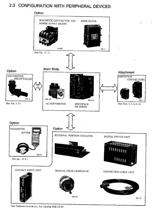
Overview
This document is a multifunctional/positioning control manual for the Yaskawa AC servo drive HR series (model CACR-HR, including rack mounted CACR-HR □□ BAB and base mounted CACR-HR □□□ BB), covering in detail the model identification, rated specifications (such as motor output power 0.07-8.2HP, drive input voltage 100-230VAC), mechanical characteristics (allowing radial/axial loads, anti vibration and anti impact performance), wiring connections (typical connections and terminal definitions for main circuit/control circuit/encoder/brake power supply, etc.) of the servo motor (M/F/G/D/S/R/P series) and servo drive I/O signal operation (2CN/5CN input/output signal timing and function), serial communication (RS422 protocol, supporting baud rates such as 9600/4800), parameter setting (100 parameters, including core parameters such as position loop gain Kp and speed loop gain Kv), display/monitoring function (LED indicator light and 7-segment digital tube status display), installation and wiring specifications, trial operation and maintenance (battery replacement, troubleshooting), while emphasizing safety precautions (such as opening the cover after 5 minutes of power outage, anti electric shock/anti scald measures), providing comprehensive guidance for the selection, installation, debugging and maintenance of servo systems.
Product Model and Configuration
1. Analysis of servo motor models (taking USAGED-13A2 as an example)
Explanation of the meaning of model segmentation
USA product prefix Yaskawa servo motor identification
G series (fully enclosed self cooling type, IP65 protection)
ED structural characteristics with encoder
13 output specification 1.3kW (corresponding to 1.7HP)
A-axis end specification with keyway
2 encoder types incremental 8192P/R
2. Analysis of servo drive models (taking CACR-HR03BAB12 as an example)
Explanation of the meaning of model segmentation
CACR-HR Product Series Yaskawa HR Series Servo Drivers
03 Output capacity 300W (0.4HP)
BAB installation and power supply B=rack mounted, A=single-phase, B=200VAC
12th Design Version 12th Design
3. Matching principle between motor and driver
Power matching: The output capacity of the driver needs to cover the rated power of the motor (such as a 300W motor matched with HR03 series driver).
Voltage matching: 100V motor (R series DS model) matches HR □□ BAB11 driver, 200V motor matches HR □□ BAB12/BB driver.
Encoder matching: The absolute encoder motor requires the driver to support battery backup (the HR series panel comes with a 3.6V battery).
Rated specifications and mechanical characteristics
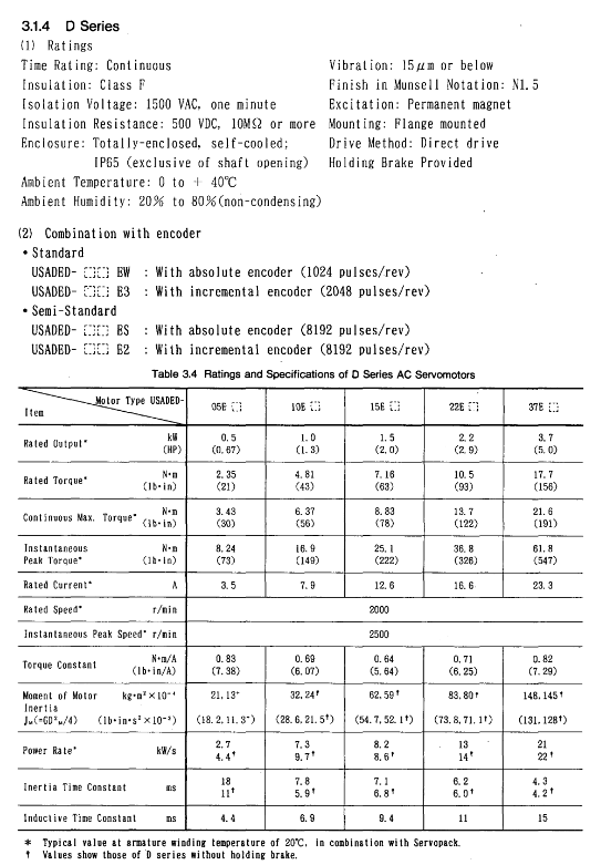
1. Core specifications of servo motors (examples by series)
Motor series model example Rated output Rated speed Rated torque Peak torque Encoder type
M-series USAMED-03B2 0.3kW (0.4HP) 1000r/min 2.84N · m 8.92N · m incremental 8192P/R
S-series USASEM-15A2 1.5kW (2.1HP) 3000r/min 4.90N · m 13.7N · m incremental 2048P/R
R series (200V) USAREM-05CS 500W (0.67HP) 3000r/min 1.59N · m 4.76N · m absolute formula 8192P/R
P Series USAPEM-07CW 750W (1.0HP) 3000r/min 2.39N · m 7.06N · m Absolute 1024P/R
2. Core specifications of servo drive
Driver model input power output current (continuous/peak) control mode protection function
CACR-HR03BAB12 single-phase 200-230VAC 2.7A/7.8A full wave rectification+PWM sine wave drive OC, OV, OL, PG disconnection, etc
CACR-HR15BB three-phase 200-230VAC 11.7A/33.0A full wave rectification+PWM sine wave drive OC, OV, OL, phase loss (O-PH), etc
CACR-HR05BAB11 single-phase 100-115VAC 5.5A/16.3A full wave rectification+PWM sine wave drive OC, OV, OL, battery low voltage (BATALM), etc
3. Mechanical characteristics (motor)
Allowable load: Radial load 78.4-1764N (such as S series 02A model 78.4N, M series 60B model 1764N), axial load 39.2-588N.
Environmental tolerance:
Temperature: 0-40 ℃ for operation, 20-60 ℃ for storage;
Vibration: below 15 μ m (10-50Hz);
Protection level: IP44 (S/R series), IP65 (M/F/G/D/P series, excluding shaft ends).
Connection and wiring
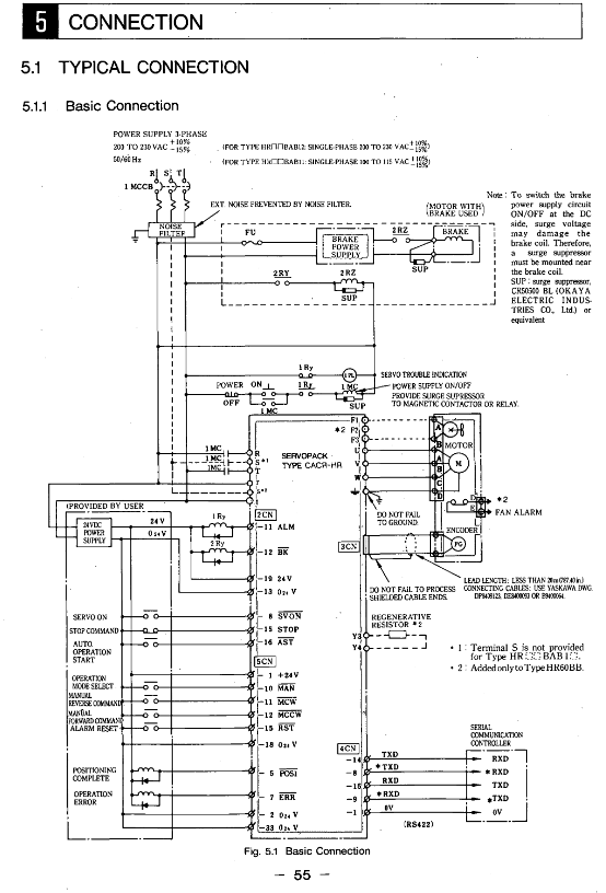
1. Typical connection circuit
Main circuit connection: three-phase/single-phase power supply → circuit breaker (MCCB) → noise filter → servo driver (R/S/T) → motor (U/V/W).
Control circuit connection:
I/O signals: 2CN (servo enable SVON, start AST), 5CN (manual operation MCW/MCCW);
Encoder: 3CN (A/B/C phase signals,+5V power supply);
Serial communication: 4CN (TXD/RXD, RS422 protocol).
2. Definition of Key Terminals (Taking 2CN as an Example)
Terminal number, signal name, type, and function
8 SVON input servo enable, main circuit transistor unlocked when ON, motor powered on
Automatic operation/zeroing start with 16 AST inputs, valid rising edge, must be maintained for ≥ 5ms
15 STOP input temporarily stops, when ON, the motor decelerates and stops according to the parameter settings
11 ALM output fault alarm, transistor cutoff during fault (normally ON)
12 BK output brake release, when servo ON, ON, release motor brake
3. Wiring specifications
Cable selection:
Main circuit: 1.25-8mm ² copper core wire (e.g. 8mm ² for HR60BB);
Signal circuit: 0.2mm ² shielded twisted pair (DP8409123 and other dedicated wires are used for encoder lines).
Grounding requirements:
Driver FG terminal → grounding electrode (Class 3 grounding, resistance ≤ 100 Ω);
Motor frame ground → driver FG terminal to avoid common ground interference.
Noise control:
Install a noise filter on the power side (such as HR03BAB with LF-205A);
The distance between power lines and signal lines should be ≥ 30cm, and wiring in the same conduit is prohibited.
Functional operations (I/O, communication, parameters)
1. I/O signal operation
Input signal timing: SVON, AST and other signals need to maintain a stable level of ≥ 5ms to avoid false triggering;
Output signal status:
POS1 (positioning completed): ON when the deviation between the current position and the target position is ≤ P6 (positioning completed width, 1-250 units);
NEAR (positioning proximity): ON when the deviation is ≤ P45 (positioning proximity width, 0-3000 units).
2. Serial communication (RS422)
Communication specifications:
Baud rate: 9600/4800/2400/1200Baud (default 9600);
Data format: 1 start bit+7 data bits+1 even check bit+1 stop bit.
Core command:
SVON: Servo Enable;
MOV ± nnnnnn: Absolute positioning (± 8-bit position data);
ZRN: Start back to zero;
PRMpp=± nnnnnnnn: Set parameters (pp=parameter number).
Multi axis control: Supports 16 axes and specifies the control object through axis addresses (1-16).
3. Parameter Setting (Example of Core Parameters)
Parameter Number, Parameter Name, Unit Range, Function Description
P1 position loop gain Kp s ⁻¹ 0-200 adjusts position control response speed, the larger the value, the faster the response (prone to oscillation)
P2 speed loop gain Kv × 2.5Hz 1-200 adjustment speed control response speed, matching system rigidity
P4 1st feed rate x 1000 units/minute 1-240000 reference speed in automatic/manual mode
When the deviation of the width unit 1-250 after P6 positioning is ≤ this value, the POS1 signal is ON
P7 motor selection -0-79 matching motor model (e.g. 32=USAREM-A5CS)
P8 encoder pulse P/R (× 4) 4096-32768 encoder pulse per revolution (absolute 8192P/R set to 32768)
Display/Monitoring and Maintenance
1. Display function
LED indicator light:
MAIN (red): residual voltage in the main circuit (slowly extinguishes after power failure);
RUN (green): Control power supply is normal (+5V normal);
ALM (red): Fault alarm (check the 7-segment digital tube code when it lights up).
7-segment digital tube:
Normal state: Display current position (PUN) and speed (NFB);
Fault status: Display code (such as OC=overcurrent, OL=overload, BAT=low battery).
2. Trial operation process
Preparation stage:
Check the wiring (main circuit/control circuit is not loose) and parameters (P7/P8/P9 matching motor and encoder);
Absolute encoder reset: Short circuit the specific pin of the encoder and release it after powering on for ≥ 2 minutes.
Test operation:
Servo Enable: Send SVON command, confirm that RUN light is on and ALM light is off;
Jogging test: Send JOG+1000 command (1000 units/minute) to confirm that the motor rotates smoothly;
Positioning test: Send MOV+10000 command and confirm that POS1 signal is ON after positioning is completed.
3. Maintenance and troubleshooting
Battery replacement: Replace the absolute encoder battery (3.6V) when the voltage is ≤ 3.3V, and replace it after power failure (to avoid data loss).
Common troubleshooting:
|Alarm code | Fault cause | Handling measures|
|OC (overcurrent) | Main circuit overcurrent (≥ 1.2 times peak current) | Check if the motor wiring and load are stuck|
|OL (overload) | Motor overload (exceeding allowable load inertia) | Reduce load inertia and acceleration rate|
|PG (Encoder Disconnected) | Encoder Cable Loose/Disconnected | Check 3CN Wiring and Encoder for Damage|
|BAT (low battery) | Absolute encoder battery voltage low | Replace 3.6V lithium battery (such as CR2450)|
Installation and environmental requirements
Motor installation:
Installation method: Both horizontal and vertical can be used, with axis centering deviation ≤ 0.03mm;
Axial load: The radial/axial load shall not exceed the specifications in Table 3.9 (such as M series 03B model radial 490N).
Driver installation:
Rack mounted (BAB): vertically installed, with a spacing of ≥ 10cm (for heat dissipation);
Base type (BB): vertically installed, avoiding direct sunlight/condensation environment.
Environmental restrictions:
Temperature: driver 0-55 ℃, motor 0-40 ℃;
Humidity: 20% -80% RH (without condensation);
Dust: Do not use in dusty or corrosive gas environments.
- OMRON
- ABB
- General Electric
- EMERSON
- Honeywell
- HIMA
- ALSTOM
- Rolls-Royce
- MOTOROLA
- Rockwell
- Siemens
- Woodward
- YOKOGAWA
- FOXBORO
- KOLLMORGEN
- MOOG
- KB
- YAMAHA
- BENDER
- TEKTRONIX
- Westinghouse
- AMAT
- AB
- XYCOM
- Yaskawa
- B&R
- Schneider
- KONGSBERG
- NI
- WATLOW
- ProSoft
- SEW
- ADVANCED
- Reliance
- TRICONEX
- METSO
- MAN
- Advantest
- STUDER
- DANAHER MOTION
- Bently
- Galil
- EATON
- MOLEX
- DEIF
- B&W
- ZYGO
- Aerotech
- DANFOSS
- Beijer
- Moxa
- Rexroth
- Johnson
- WAGO
- TOSHIBA
- BMCM
- SMC
- HITACHI
- HIRSCHMANN
- Application field
- XP POWER
- CTI
- TRICON
- STOBER
- Thinklogical
- Horner Automation
- Meggitt
- Fanuc
- Baldor
- SHINKAWA
- Other Brands
- UniOP
- KUKA
- Iba
- Beckhoff
-
 Basler D90 96801 100 PCB Card
 -
 Basler XR2002F Voltage Regulator (110 VAC, 48-480 Hz)
 -
 Basler SR8A-2B14B3A Regulator
 -
 Basler 9561500100 Module
 -
 Basler DECS-400 BE1-11 System
 -
 Basler DECS-100-B15 Excitation Control
 -
 Basler SCP 210 Frequency Controller
 -
 Basler SR4A-2B15B3A Static Voltage Regulator
 -
 Basler BE1-32R Power Relay
 -
 Basler PIA2400-17GM Power Interface Adapter
 -
 Basler MVC 232 Manual Voltage Control Module
 -
 Basler SSR 32-12 Static Voltage Regulator
 -
 Basler 5MW AVR Generator Voltage Regulator
 -
 Basler VR63-4B Voltage Regulator
 -
 Basler DECS-100-A05 AVR for Engine Generator
 -
 Basler DECS-100-B15 Automatic Voltage Regulator
 -
 Basler BE1-32R Directional Power Relay
 -
 Basler BE1-87B Differential Relay
 -
 Basler UFOV 260A Protective Module
 -
 Basler 9-2614-02-100 PCB Rev M
 -
Basler DECS-100-B15 Digital AVR
-
 Basler 9284900103 PS DECS-400N
 -
 Basler D4N3H1U Intertie Protection
 -
 Basler DECS-100-B15 A15 AVR
 -
 Basler KR4F Voltage Regulator
 -
 Basler BE26434 T14 Transformer
 -
 Basler SR8A-2B15B3A Regulator
 -
 Westinghouse 774B472A12 AR Relay
 -
Basler DECS-100-B15 AVR
-
Basler XR2002F Regulator 110V
-
Basler SR125-E Static Regulator
-
 Basler SSR 125-12 Regulator
 -
 Basler MOC2599 Motor Pot
 -
 Basler BE1-DFPR Feeder Relay
 -
 Basler CBS 305 Current Boost
 -
 Basler BE1-25 AutoSync
 -
 Basler MVC 300 Voltage Control
 -
 Basler BE3-25A AutoSync
 -
 Basler KR7FF Static Regulator
 -
 Basler 90-49000-100 Regulator
 -
 Basler 880 kVA Dry Type Transformer Specs
 -
 Basler Electric BE1-25 Sync-Check Relay Specs
 -
 Basler SSR 125-12 Voltage Regulator Specs
 -
 Basler Electric BE1-851 Overcurrent Relay Review
 -
Basler Electric 149D930G02 Control Sub-Assembly
-
 Basler Electric BE1-81O/UT Frequency Relay Specs
 -
 Basler Electric BE1-51/27C Overcurrent Relay
 -
 Basler Electric 149D956G02 Industrial Component
 -
Basler Electric BE1-51A Overcurrent Relay Specs
-
 Basler Electric BE1-40Q Loss of Excitation Relay
 -
 Basler DECS-200 Excitation Control System
 -
 Basler DECS-200 Voltage Regulator 56-277V AC / 125V DC
 -
Basler BE1-87T Transformer Differential Relay
-
 Basler RDP-110-S1 Protection Relay
 -
 Basler BE1-700V Digital Protective Relay
 -
 Basler BE1-951 Overcurrent Protection System
 -
 Basler DECS-300 Digital Excitation Control
 -
 Basler DECS-200 Digital Excitation Control
 -
 Basler DECS-200-1C Excitation Control System
 -
Basler DECS-200-1L Digital Excitation Control
-
 Basler Electric BE1-GPS Generator Protection System
 -
Basler Electric DECS-200-1C Digital Excitation Controller
-
 Basler Electric DECS125-15 Excitation Control with Power Module
 -
 Basler Electric BE1-87G Differential Relay
 -
 Basler Electric BE1-11 Protection System I5A3M2P2N0EA00
 -
Basler Electric DECS-200-1C Excitation Control System
-
Basler Electric BE1-11g Generator Protection Relay
-
Basler Electric DECS 125-15-B2C1 V2.0.9 Excitation Control
-
 Basler Electric BE1-81O/UT3ED1JA7N2F Frequency Relay
 -
Basler Electric BE1-81O/UT3EE1YB7N1F Frequency Relay
-
 Basler Electric DECS-200-1L Digital Excitation Control System
 -
Basler DECS125-15-B2C1 Excitation Control
-
 Basler 9507900205 SSR Retrofit Voltage Regulator
 -
 Basler BE2000E Digital Voltage Regulator
 -
 Basler BE1-GPS Generator Protection System
 -
Basler DECS-250-CN1CN1N Digital Excitation Control
-
 Basler DGC-2020 Genset Controller
 -
 Basler BE1-81O UT3ED1LA7N0F Frequency Relay (Variant)
 -
 Basler BE1-81O UT3EE1YA9S0F Frequency Relay (Variant)
 -
Basler BE1-81O Over/Under Frequency Relay
-
Basler DECS125-15 Digital Excitation Control
-
Basler Electric BE1-951 Overcurrent Protection System
-
 Basler Electric BE1-700V Digital Protective Relay
 -
 Basler Electric APR63-5 Automatic Voltage Regulator
 -
Basler Electric BE1-851 Overcurrent Protection System
-
Basler Electric DECS-250-LN1SN1N Excitation Control
-
 Basler Electric BE1-87T Transformer Differential Relay
 -
Basler Electric DECS-200-1L Excitation Control System
-
 Basler Electric 9310300100 DECS-300 Excitation Control
 -
 Basler Electric SSE-N 125-4.5KW Shunt Exciter Regulator
 -
 Basler Electric DGC-2020HD-5NS1DNSBA Genset Controller
 -
Basler Electric BE1-81-O/UT3EE1JB7N1F Frequency Relay
-
Basler Electric BE1-81T1EE1WA0N1F Frequency Relay
-
 Basler Electric BE1-25M1EA6PN5R1F Sync-Check Relay
 -
 Basler Electric BE1-GPS Generator Protection System
 -
Basler Electric DECS-250-LN1SN1N Excitation Control Rev V
-
 Basler Electric DECS-250-CN2CN1N Excitation Control
 -
Basler Electric BE1-50/51B-207 Overcurrent Relay
-
Basler Electric DECS-300-C0N0 Excitation Control System
-
Basler Electric DECS-200 Digital Excitation Control System
-
Basler Electric DECS-250-LN1CN1N Excitation Unit
-
Basler Electric DECS-250 LN2SA1D Excitation Unit Specs
-
Basler Electric BE1-87T Transformer Relay Review
-
Basler Electric BE1-11 Protection System
-
Basler Electric BE1-GPS100-E4N1H1N Protection System
-
 Allen-Bradley 442G-MABH-R Safety Module
 -
 Beckhoff CX1030-0111 PLC Assembly Profile
 -
 FANUC IC693CPU364 PLC Module
 -
 Orange Denmark Type 200816 220 PLC Specs
 -
 OMRON C200H-SNT31 Sysmac PLC Module
 -
 Allen Bradley 20AB022A3AYNANC0 PowerFlex 70
 -
 OMRON C200HW-PCU01 Position Control Unit
 -
 ABB AO845A-eA Analog Output Module
 -
 OMRON CJ1M-CPU22 CPU Unit
 -
 Allen Bradley 100-E265ED11 Contactor
 -
 Honeywell 51304511-100 Interface Module
 -
 SOLEXY BXF3S0101N0018 Gateway Module
 -
 OMRON CJ2H-CPU65 CPU Unit
 -
 Automation Direct GS2-45P0 AC Drive
 -
 M68-2000 2-Axis Motion CNC Controller
 -
 OMRON CJ1M-CPU11 V3.0 PLC CPU Unit
 -
 OMRON CJ1W-NC413 4-Axis Positioning Controller
 -
 OMRON 3G2A3-PRO16 Programming Console HMI
 -
 Siemens 3VT8440-2AA04-2GA2 Molded Case Circuit Breaker
 -
 Siemens 3RT5045 Contactor Series
 -
 OMRON C200HS-CPU01-E SYSMAC PLC Controller
 -
 OMRON C500-NC103-E Positioning Control Unit
 -
 OMRON CJ1W-TC001 Temperature Control Unit


