
How to troubleshoot Yokogawa OR8EFG KCl filled ORP sensor (IM12C07J01-01E)?
As a 'simple device', OR8EFG must meet the following compliance conditions before it can be used in hazardous areas:
Supporting equipment: It must be used in conjunction with transmitters with built-in isolation functions (such as FLXA202-D - □ - D-CB -...) or systems with isolation safety barriers to avoid risks introduced by non isolated circuits;
Temperature limit: Depending on the ambient temperature (Ta) and temperature level, the upper limit of the process temperature varies (for example, when T6 level Ta=40 ℃, FLXA202 can be used with an upper limit of 16 ℃); T3 level Ta=upper limit of 105 ℃ at 40 ℃);
Electrostatic protection: Avoid wiping the sensor with a dry cloth to prevent the accumulation of static electricity from causing explosions; The titanium material solution grounding terminal (- TN suffix) can eliminate the risk of impact friction sparks;
Installation and wiring process
1. Preparation before installation
(1) Unpacking and Inspection
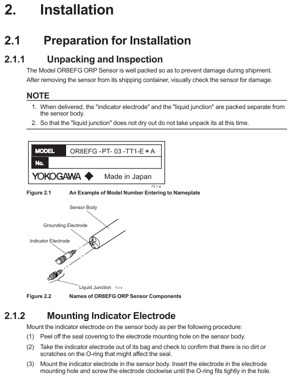
After unpacking, confirm that the sensor body, indicator electrode, liquid interface, and KCl storage tank (if ordered) are not damaged, and verify that the model suffix matches the order (such as electrode material and cable length);
The indicator electrode and the liquid interface are packaged separately, and the liquid interface should be kept moist. After unpacking, it should not be taken out temporarily to avoid drying and affecting performance;
Check the integrity of attachments: installation bracket (such as PH8HS), KCl solution/powder (accessory OR8AX contains 3 bags of 250mL powder), cable sealing glass, etc.
(2) Installation site selection requirements
Avoid installing in dead zones, bubble accumulation areas, or locations with high flow rates (>2 m/s) to prevent measurement response delays or electrode wear;
If the medium contains corrosive gases (such as ammonia and hydrogen sulfide) or the temperature is greater than 80 ℃, a flow-through or immersion bracket must be used and cannot be suspended separately;
The installation in hazardous areas must comply with local electrical regulations (such as ANSI/ISA-RP12.06.01), ensure that the grounding resistance is ≤ 1 Ω, and avoid potential difference sparks.
2. Core installation steps (taking a flow-through bracket as an example)
(1) Assembly of electrode and liquid interface
Installation indicator electrode: Remove the sealing tape from the installation hole of the sensor body electrode, take out the platinum/gold electrode, check that the O-ring is not damaged, and then screw it clockwise into the installation hole until the O-ring is tightly sealed;
Pre installed liquid interface: Remove the sealing tape from the installation hole of the liquid interface, gently screw the liquid interface into 2-3 turns (not tightened temporarily), and reserve a channel for filling with KCl solution;
Connect KCl storage tank: If it is a universal type (- TT1), fix the storage tank on a 2-inch pipe through a bracket, connect the KCl supply pipe of the sensor, and use the accompanying needle to puncture the top of the storage tank (balance air pressure); If it is a medium pressure type (- TT2), an external air pressure regulator (slightly higher than the maximum process pressure) is required, and an air pipeline should be connected.
(2) KCl solution filling
Invert the sensor (below the height of the storage tank) to allow KCl solution to flow from the storage tank into the sensor body;
When the solution overflows from the installation hole of the liquid interface, tighten the liquid interface clockwise (to avoid residual air) to complete the filling;
The medium pressure storage tank needs to be replenished to a distance of 30-40 mm from the top to prevent the solution from overflowing during pressurization.
(3) Bracket assembly and fixation
Remove the protective foam of the circulating bracket (PH8HF), insert the sensor tip into the bracket, and tighten the fixing nut (ensure the O-ring compression seal);
Connect the process pipeline: first open the inlet valve, then open the outlet valve to avoid medium impact on the sensor; Under medium pressure conditions, the storage tank needs to be pressurized first before the process medium is introduced.
3. Wiring specifications
The OR8EFG cable contains 4-core wires and needs to be connected to the transmitter (such as FLXA202) according to the terminal definition. The wiring method may vary slightly depending on the terminal type (pin/ring):
Corresponding terminal for cable core color function (taking FLXA202 as an example) Remarks
The red indicator electrode (GE) at terminal 15 is transmitting ORP signals, and it is necessary to ensure that the wiring is secure to avoid signal interference;
The brown reference electrode (RE) terminal 13 forms a measurement circuit with the indicator electrode and needs to be grounded separately;
The black liquid interface/grounding (SE) terminal 14 is used to eliminate the grounding potential difference and must be reliably grounded;
Connect the green common terminal (G) 16 to the transmitter common terminal to ensure the integrity of the circuit;
Cable sealing: When passing through the transmitter cable inlet, a matching glass should be used, and the nut should be tightened to the seal (to avoid damaging the cable due to over tightening);
- OMRON
- ABB
- General Electric
- EMERSON
- Honeywell
- HIMA
- ALSTOM
- Rolls-Royce
- MOTOROLA
- Rockwell
- Siemens
- Woodward
- YOKOGAWA
- FOXBORO
- KOLLMORGEN
- MOOG
- KB
- YAMAHA
- BENDER
- TEKTRONIX
- Westinghouse
- AMAT
- AB
- XYCOM
- Yaskawa
- B&R
- Schneider
- KONGSBERG
- NI
- WATLOW
- ProSoft
- SEW
- ADVANCED
- Reliance
- TRICONEX
- METSO
- MAN
- Advantest
- STUDER
- DANAHER MOTION
- Bently
- Galil
- EATON
- MOLEX
- DEIF
- B&W
- ZYGO
- Aerotech
- DANFOSS
- Beijer
- Moxa
- Rexroth
- Johnson
- WAGO
- TOSHIBA
- BMCM
- SMC
- HITACHI
- HIRSCHMANN
- Application field
- XP POWER
- CTI
- TRICON
- STOBER
- Thinklogical
- Horner Automation
- Meggitt
- Fanuc
- Baldor
- SHINKAWA
- Other Brands
- UniOP
- KUKA
- Iba
- Beckhoff
-
 Basler BE1-57/27R Solid State Protective Relay
 -
 Basler BE3-25AX Time Overcurrent Relay
 -
 BASLER ELECTRIC BE1-24/A1EF1JC1N0F / BE124A1EF1JC1N0F Overvoltage Relay
 -
Basler Electric Solid State Protective Relay BE1-32R Style B2ED1PB0N0F
-
 Basler BE3-51-3E1E1 9320000110 24VDC Overcurrent Relay
 -
 Basler UFOV 260A Underfrequency Overvoltage Module
 -
 Basler 50F4EA1PA0N0F Instantaneous Overcurrent Relay
 -
 Basler BE1-50 Instantaneous Overcurrent Relay
 -
 Basler BE1-32 Solid State Protective Relay
 -
 Basler SCP 250-G-60 VAR Power Factor Controller
 -
Basler BE1-59N A5EE1KC0N0F Ground Fault Relay
-
Basler BE1-79A Reclosing Relay
-
Basler BE1-32R E1EA1OA0N0F Reverse Power Relay
-
 Basler DCQA-103 DCQC104-1 CMX-7D Circuit Board
 -
 Basler SSR125-12 Static Regulator 918500102
 -
 Basler 90 17709 112 Regulator Control Board
 -
 Basler AVC63-4 AVC634 Voltage Regulator
 -
 Basler 9 1049 04 100 PC Board Control Module
 -
 Basler SR4A-2B03B3A Static Voltage Regulator
 -
 Basler SR8A-2B15B3A Static Voltage Regulator
 -
 Basler KR7FFX Static Regulator 840V
 -
 Basler EL200-7 Voltage Regulator 90-660VAC 7A
 -
 Basler PRP210-1 Reverse Power Relay 9056300102
 -
 Basler SSR 63-12 Static Regulator 600VAC
 -
 Basler 9289901106 Digital Board
 -
Basler DECS100 Voltage Regulator DECS100A01
-
 Basler Electric CEM-2020 Contact Expansion Module
 -
Basler Electric BE3-25-1 C1 N4 Synchronizing Check Relay
-
 Basler Electric ACA2000-50GM GigE Camera 2MP 50fps
 -
 Basler Electric ACA2240-20GMSYM GigE Camera Sony IMX264
 -
 Basler BE1-50G Ground Overcurrent Relay
 -
 Basler PRS250 Veri-Sync Relay
 -
Basler MOC2199 Output Module
-
 Basler UFOV 260A Underfrequency Overvoltage Module
 -
 Basler BE-15482-001 Control Module
 -
Basler LSP4-7 Protective Relay
-
 Basler SCP 250-G-60 VAR Power Factor Controller
 -
Basler BE146N Negative Sequence Overcurrent Relay
-
Basler APR63-5 Automatic Voltage Regulator
-
Basler 9507900107 SR8A Retrofit Voltage Regulator
-
Basler BE1-320 Directional Power Relay
-
 Basler KR7F Voltage Regulator 9116200100
 -
Basler UFOV 260A Overvoltage Protective Module
-
 Basler AEC63-7 Analog Excitation Controller
 -
Basler 9992D90G01 Control Module
-
 Basler 6966D22G01 Control Board
 -
Basler 6965D40G01 Control Board
-
 Basler BE1-50/51M-104 Overcurrent Relay
 -
 Basler BE1-BPR Programmable Breaker Relay
 -
 BASLER Electric SSR 125-9 1256 00 102 Static Voltage Regulator
 -
 Basler Electric MVC 112 Manual Voltage Control
 -
 Basler Electric 9321000102 Control Module
 -
 Basler Electric RA-70-MDCT7 Rectifier Assembly
 -
 Basler Electric ACA1300-60GM GigE Camera
 -
 Basler Electric 6427C85G01 Interface Board
 -
Basler Electric 6965D05G01 Control Board
-
Basler Electric ACA2500-14UC Current Transducer
-
 Basler Electric 9170206111 Protective Relay
 -
 Basler Electric BE1-11-G6D1M1J1P0E000 Protection Relay
 -
Basler Electric BE1-50/51B-107 Overcurrent Relay
-
 Basler 9121000106 Voltage Controller
 -
 Basler B3E-E1P-A0N0F Solid State Protective Relay
 -
 Basler 9121000106 Manual Voltage Control
 -
Basler PRP320 Motor Pull-out Relay
-
 Basler SSE-N 250-9KW Shunt Exciter Regulator
 -
 Basler BE1-50-51B-107 Overcurrent Relay
 -
 BASLER ELECTRIC MVC 108 MANUAL VOLTAGE CONTROL MODULE 9 0370 00 102
 -
Basler BE1-59N-A7E-D1J-D0N0F Ground Overvoltage Relay
-
Basler BE1-46N-G1E-B8P-B0N0F Negative Sequence Overcurrent Relay
-
Basler BE1-951 Overcurrent Protection System
-
 Basler Electric MOC2199 Motor Operated Potentiometer
 -
 Basler Electric BE1-60 Voltage Balance Solid State Relay B1FA1C1M1F
 -
Basler Electric BE1-67N Directional Overcurrent Relay
-
Basler Electric PIA2400-17GM Interface Module
-
 Basler Electric V6RAB Rectifier Module
 -
Basler Electric BE1-32R Reverse Power Relay B2E E1R A0N1F
-
Basler Electric IFM-150 Firing Circuit Chassis 120V AC
-
 Basler Electric IFM-102 Firing Circuit Chassis 120V AC
 -
 Basler Electric 9170206111 NSNP Control Module
 -
Basler Electric SSR 63-12 Static Voltage Regulator
-
 Basler UFOV 260A Overvoltage Protective Module
 -
Basler SCA1300-32GM CCD Camera Lens Enclosure
-
 Basler BA1-27 Under Voltage Relay
 -
Basler 149D866G06 Control Board
-
 Basler 9072300130 Power Supply Module
 -
Basler CBS 305 Current Boost System
-
 Basler BE1-60 Voltage Balance Relay
 -
 Basler Electric CBS 212 Current Boost System Sensing 120/240VAC 50/60Hz 10VA
 -
 Basler MVC-300 Manual Voltage Control Unit
 -
Basler SSR125-12 Static Voltage Regulator 918500102
-
Basler SR32A2B05B3E Static Voltage Regulator
-
Basler Electric BE1-59N Ground Fault Overvoltage Relay
-
 Basler Electric 9110000113 Excitation Module
 -
Basler Electric 90-72300-114 Control Accessory
-
Basler Electric PRS-250 Protection Relay System
-
Basler Electric BE1-50/51M-109 Overcurrent Relay
-
 Basler Electric SR4A1B10B3E Static Voltage Regulator
 -
 Basler Electric CBS 212 Current Boost System
 -
Basler Electric SR32A2B05B3E Static Voltage Regulator
-
Basler Electric MOC2207 Motor Operated Potentiometer
-
 Basler Electric SR4A1B05A3E Static Voltage Regulator
 -
Basler Electric BE1-32R Power Relay B2EE1PA0N1F
-
Basler BEI-81 Underfrequency Relay
-
Basler CBS 212A Current Boost System
-
Basler SSR 63-12 Static Voltage Regulator
-
 Basler DGC-2020 Digital Genset Controller
 -
Basler BE1-32 Reverse Power Relay
-
 Basler BE1-50/51B-207 Overcurrent Relay
 -
Basler BE1-951 Overcurrent Protection System
-
 Basler 9073800-103 Power Supply
 -
Basler SCA1300-32FC CCD Camera
-
Basler 9073800-103 Power Supply
-
Basler SCA1300-32FC CCD Camera
-
 Basler L304KC Protective Relay
 -
 Basler BE3-25-1S1N4 Time Overcurrent Relay
 -
Basler 9032300113 Excitation Support System
-
Basler BE1-59N Ground Overvoltage Relay
-
Basler MVC-300 Manual Voltage Control Unit
-
Basler MOC2102 Potentiometer
-
 Basler BE1-87G Generator Differential Relay
 -
 Basler Electric DECS-200 Digital Excitation Control System
 -
Basler Electric DECS 125-15-B2C5 Digital Excitation System
-
 Basler Electric PLA2400-12GM Power Supply
 -
Basler Electric BE1-50/51B-235 Overcurrent Relay
-
Basler Electric BE1-27/59 Undervoltage Overvoltage Relay
-
Basler Electric CEM-2020 Contact Expansion Module
-
Basler Electric BE1-32R Solid State Power Relay
-
 Basler Electric BE1-700 Digital Generator Management Relay


