
YASKAWA MP2000 series machine controller communication module
YASKAWA MP2000 series machine controller communication module
The entire process of starting the communication module
Step 1: Prepare using the machine
Essential equipment: MP2000 series controller, communication module, communication partner device, dedicated cable, computer with MPE720 installed
Controller compatibility: MP2200 (JEPMC-BU2200/BU2210, maximum of 8 modules), MP2300 (JEPMC-MP2300, maximum of 3 modules), MP210M (JAPMC-MC2140, expansion board required, maximum of 8 modules), MP2500MD (JEPMC-MP2540-D , expansion board required, maximum of 8 modules)
Step 2: Module installation and disassembly
Installation steps: Power off → Remove the machine controller battery cover → Remove the optional module cover → Align the guide rail and insert the module → Install the cover → Power on
Disassembly steps: Power off → Backup program → Remove cable → Remove battery cover → Remove cover → Use battery cover protrusion to pry module → Pull out module
Step 3: Communication Manager Settings
Supported port types: Serial (RS-232C), Ethernet, Ethernet (LP), CP-215
Key setting example (Ethernet): Set the computer IP to 192.168.1.2 and subnet mask to 255.255.255.0; Set the Logical PT to Ethernet and fill in the computer IP address for the Communication Manager
Step 4: Automatic Configuration Execution
Trigger method: Set "CNFG" to ON and restart MP2200/MP2300; MP210M/MP2500MD operated through the MPE720 menu
Result difference:
CNFG Initiate Results
The ON module has been updated, and all communication modules are configured according to default settings
The ON/OFF module has been updated, with existing modules retaining their configuration and new modules using default settings
Step 5: MPE720 Startup and Transfer Definition
Ver.6: Online → Communications Setting → Select Logical Port → Set Parameters
Ver.5.xx: Start MPE720 → Open PLC folder → Properties → Network → Check OnLine → Select logical port
Transfer definition: Open the module composition definition screen → double-click the corresponding module → set parameters → save to flash memory

Detailed explanation of transmission mode and protocol
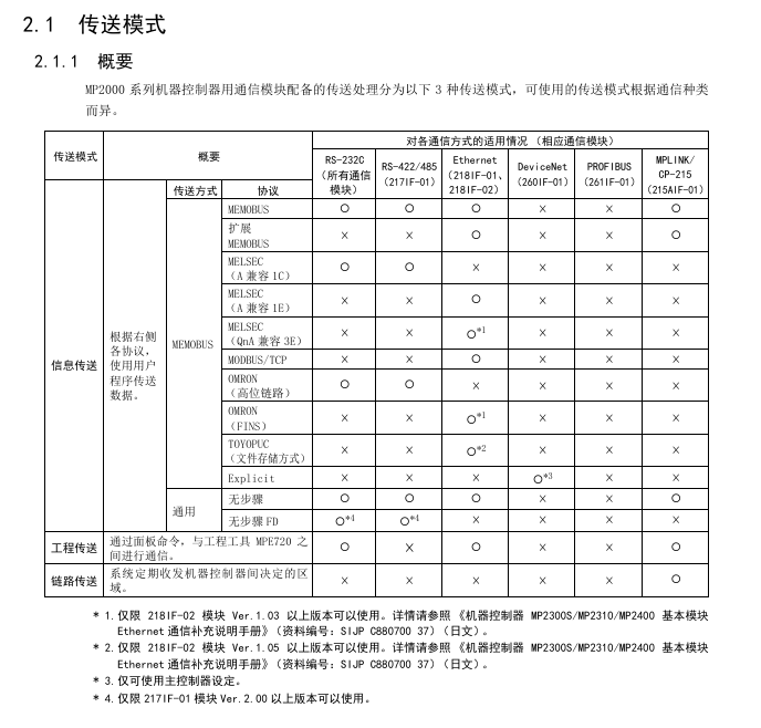
Classification of transmission modes
Mode applicable communication mode (module) core characteristics
Information transmission RS-232C (all), Ethernet (218IF-01/02), MPLINK (215AIF-01) event triggered, using MSG-SND/MSG-RCV functions
Engineering transmission RS-232C (all), Ethernet (218IF-01/02), MPLINK (215AIF-01) panel commands+MPE720 for program transmission
Link Transport MPLINK (215AIF-01) regularly sends and receives, only supported by 215AIF-01
Core Communication Protocol
MEMOBU: Yaskawa standard, main controller specifies sub controller address communication, function codes include 01H (read winding), 03H (read hold register), etc., supporting 1-2000 bits (bit data), 1-125 words (word data)
Extended MEMOBU: MEMOBU extension, adding function codes such as 09H (extended read hold register), transmitting 1-508 words at once, supporting MEMOBU/general information mode
MELSEC: Compatible with Mitsubishi A-series, supports communication between CPUs and fixed buffer communication, with function codes corresponding to ACPU universal commands (such as WR → 01H/02H)
MODBUS/TCP: Industrial Ethernet protocol, supports 1-2000 bits (read winding), 1-125 words (read register), 218IF-01/02 automatic conversion protocol
No steps: Directly transfer data from the M register, divided into word (1-254 words) and byte (1-508 bytes) units, with no response
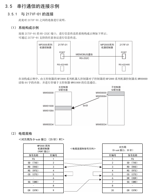
Serial communication (taking 217IF-01 as an example)
Ports and protocols
Interface: RS-232C (PORT, 9-pin), RS-422/485 (14 pin)
Supporting protocols: MEMOBU, MELSEC, OMRON, Stepless, Stepless FD (Full Duplex, Maximum Received 5080 Words)
Transmission definition parameters
Example of Parameter Setting Content
Transmission Protocol MEMOBU/MELSEC/OMRON/Stepless MEMOBU
Master (Address 0)/Slave (Address 1~63) Slave, Address 1
Baud rate 9600/19200bps 19200bps
Data length 7/8 bits 8 bits
Parity Even/Odd/None Even
Connection Example
Connected to MELSEC: RS-232C (pin 2=TXD, 3=RXD) of 217IF-01 connected to Mitsubishi AJ71UC24 (pin 2=RXD, 3=TXD), MELSEC set station number 01, baud rate 19200bps
Connected to frequency converter: RS-485 (pin 3=RX+, 4=RX -, 8=TX+, 9=TX -) of 217IF-01 is connected to VS-616G5, and frequency converter H5-01=1 (address) H5-02=9600bps
Key module characteristics (218IF-01/02, 260IF-01)
218IF-01 module
Interface: RS-232C (PORT), Ethernet (10Base-T, RJ45)
Specification: Ethernet transmission speed of 10Mbps, half duplex; RS-232C maximum transmission 15m
Ethernet settings: IP address (default 192.168.1.1), subnet mask, connection parameters (TCP/UDP, ports 256~65535)
218IF-02 module
Interface: RS-232C (PORT), Ethernet (100Base TX/10Base-T)
Advantages: Supports Ethernet (LP) ports, higher engineering communication speed, maximum transmission of 100m (100Base TX)
260IF-01 module
Communication: DeviceNet, supports Explicit protocol, main controller settings
Specification: Maximum number of nodes 64, transmission speed 125/250/500kbps
Key issues
Question 1: There are two triggering methods for the automatic configuration of MP2000 series communication modules. Which controllers are they applicable to? What are the differences in configuration results?
Answer:
Applicable controllers:
Dial switch trigger: suitable for MP2200 and MP2300, triggered by turning on the "CNFG" toggle switch of the machine controller and restarting the power supply;
MPE720 operation trigger: applicable to MP210M and MP2500MD. After starting MPE720, select Order → Self Configure All Modules/Module Self Configuration on the Module Configuration screen to trigger.
Differences in configuration results:
Specific operation results of triggering method
The dip switch (MP2200/MP2300) CNFG=ON, Initiate=ON module composition definition is updated, and all detected communication modules are configured according to default values
The dip switch (MP2200/MP2300) CNFG=ON and Initialize=OFF modules constitute a definition update. Modules that already have transmission definitions retain their current definitions, while newly detected modules use default values
MPE720 (MP210M/MP2500MD) automatically configures all module composition definitions and updates them. Existing defined modules retain their current definitions, while newly detected modules use default values
MPE720 (MP210M/MP2500MD) automatically configures a single module with only selected module configurations and transmission definitions. Existing definitions are reserved, and newly detected ones use default values
Question 2: What are the core differences in functionality and usage between the IF-01 module, which supports two protocols: Stepless and Stepless FD?
Answer: The core differences between the two are reflected in communication methods, number of channels, data processing capabilities, etc., as follows:
Comparing dimensions without steps or steps FD
Communication method: Half duplex (cannot transmit/receive simultaneously), Full duplex (can transmit/receive simultaneously)
1 information channel (MSG-SND/MSG-RCV dual-use) 2 channels (1 dedicated for sending and 1 dedicated for receiving)
The maximum data size for both sending and receiving is 254 words. Sending 254 words and receiving a maximum of 5080 words (20 buffers, each buffer containing 508 words)
Data exception handling: If one byte in one message is abnormal, all data will be discarded. Only the abnormal byte will be discarded, and normal data will be retained. The exception will be reported to the MSG-RCV function
Wiring requirements: Half duplex wiring (such as RS-485 2-wire system), full duplex wiring (such as RS-485 4-wire system, separate transmission/reception lines)
Suitable for simple one-way communication scenarios that require high-speed simultaneous transmission and reception, such as real-time data acquisition and control
Channel number setting: MSG-SND/MSG-RCV are both set to 1. MSG-SND is set to 1, and MSG-RCV is set to 2
Question 3: The Ethernet communication of the IF-01 module supports two connection types, TCP and UDP. How to choose? What are the precautions for using these two types under a step-by-step protocol?
Answer:
Selection criteria for connection type:
TCP: a connection type protocol that requires the establishment of a connection, supports data confirmation, error retransmission, flow control, and has high communication quality. It is suitable for scenarios that require high data reliability, such as control instruction transmission;
UDP: A connectionless protocol that does not require establishing a connection, has simple processing, fast communication speed, and is suitable for scenarios that require high real-time performance and can tolerate a small amount of data loss (such as real-time status monitoring).
Notes under the Stepless Protocol:
Attention to TCP usage:
TCP is a byte stream protocol, and continuous transmission of data may result in the synthesis of data packets. The receiving side cannot recognize the data boundary and measures need to be taken (such as setting a transmission interval of more than 1 second, establishing command response protocols, and avoiding packet segmentation);
Each connection only has one receive buffer, and before receiving data, the MSG-RCV function is used to read out old data to avoid new data overwriting old data.
UDP usage precautions:
No connection confirmation, sending to a non-existent socket will result in an error. It is necessary to ensure that the other party's device is online and the port is correct;
The receiving interval should be greater than twice the execution period of the MSG-RCV function (if the function period is less than 5ms, the sending interval should be set to 12ms or more) to avoid data coverage.
- OMRON
- ABB
- General Electric
- EMERSON
- Honeywell
- HIMA
- ALSTOM
- Rolls-Royce
- MOTOROLA
- Rockwell
- Siemens
- Woodward
- YOKOGAWA
- FOXBORO
- KOLLMORGEN
- MOOG
- KB
- YAMAHA
- BENDER
- TEKTRONIX
- Westinghouse
- AMAT
- AB
- XYCOM
- Yaskawa
- B&R
- Schneider
- KONGSBERG
- NI
- WATLOW
- ProSoft
- SEW
- ADVANCED
- Reliance
- TRICONEX
- METSO
- MAN
- Advantest
- STUDER
- DANAHER MOTION
- Bently
- Galil
- EATON
- MOLEX
- DEIF
- B&W
- ZYGO
- Aerotech
- DANFOSS
- Beijer
- Moxa
- Rexroth
- Johnson
- WAGO
- TOSHIBA
- BMCM
- SMC
- HITACHI
- HIRSCHMANN
- Application field
- XP POWER
- CTI
- TRICON
- STOBER
- Thinklogical
- Horner Automation
- Meggitt
- Fanuc
- Baldor
- SHINKAWA
- Other Brands
- UniOP
- KUKA
- Iba
- Beckhoff
-
 Basler D90 96801 100 PCB Card
 -
 Basler XR2002F Voltage Regulator (110 VAC, 48-480 Hz)
 -
 Basler SR8A-2B14B3A Regulator
 -
 Basler 9561500100 Module
 -
 Basler DECS-400 BE1-11 System
 -
 Basler DECS-100-B15 Excitation Control
 -
 Basler SCP 210 Frequency Controller
 -
 Basler SR4A-2B15B3A Static Voltage Regulator
 -
 Basler BE1-32R Power Relay
 -
 Basler PIA2400-17GM Power Interface Adapter
 -
 Basler MVC 232 Manual Voltage Control Module
 -
 Basler SSR 32-12 Static Voltage Regulator
 -
 Basler 5MW AVR Generator Voltage Regulator
 -
 Basler VR63-4B Voltage Regulator
 -
 Basler DECS-100-A05 AVR for Engine Generator
 -
 Basler DECS-100-B15 Automatic Voltage Regulator
 -
 Basler BE1-32R Directional Power Relay
 -
 Basler BE1-87B Differential Relay
 -
 Basler UFOV 260A Protective Module
 -
 Basler 9-2614-02-100 PCB Rev M
 -
Basler DECS-100-B15 Digital AVR
-
 Basler 9284900103 PS DECS-400N
 -
 Basler D4N3H1U Intertie Protection
 -
 Basler DECS-100-B15 A15 AVR
 -
 Basler KR4F Voltage Regulator
 -
 Basler BE26434 T14 Transformer
 -
 Basler SR8A-2B15B3A Regulator
 -
 Westinghouse 774B472A12 AR Relay
 -
Basler DECS-100-B15 AVR
-
Basler XR2002F Regulator 110V
-
Basler SR125-E Static Regulator
-
 Basler SSR 125-12 Regulator
 -
 Basler MOC2599 Motor Pot
 -
 Basler BE1-DFPR Feeder Relay
 -
 Basler CBS 305 Current Boost
 -
 Basler BE1-25 AutoSync
 -
 Basler MVC 300 Voltage Control
 -
 Basler BE3-25A AutoSync
 -
 Basler KR7FF Static Regulator
 -
 Basler 90-49000-100 Regulator
 -
 Basler 880 kVA Dry Type Transformer Specs
 -
 Basler Electric BE1-25 Sync-Check Relay Specs
 -
 Basler SSR 125-12 Voltage Regulator Specs
 -
 Basler Electric BE1-851 Overcurrent Relay Review
 -
Basler Electric 149D930G02 Control Sub-Assembly
-
 Basler Electric BE1-81O/UT Frequency Relay Specs
 -
 Basler Electric BE1-51/27C Overcurrent Relay
 -
 Basler Electric 149D956G02 Industrial Component
 -
Basler Electric BE1-51A Overcurrent Relay Specs
-
 Basler Electric BE1-40Q Loss of Excitation Relay
 -
 Basler DECS-200 Excitation Control System
 -
 Basler DECS-200 Voltage Regulator 56-277V AC / 125V DC
 -
Basler BE1-87T Transformer Differential Relay
-
 Basler RDP-110-S1 Protection Relay
 -
 Basler BE1-700V Digital Protective Relay
 -
 Basler BE1-951 Overcurrent Protection System
 -
 Basler DECS-300 Digital Excitation Control
 -
 Basler DECS-200 Digital Excitation Control
 -
 Basler DECS-200-1C Excitation Control System
 -
Basler DECS-200-1L Digital Excitation Control
-
 Basler Electric BE1-GPS Generator Protection System
 -
Basler Electric DECS-200-1C Digital Excitation Controller
-
 Basler Electric DECS125-15 Excitation Control with Power Module
 -
 Basler Electric BE1-87G Differential Relay
 -
 Basler Electric BE1-11 Protection System I5A3M2P2N0EA00
 -
Basler Electric DECS-200-1C Excitation Control System
-
Basler Electric BE1-11g Generator Protection Relay
-
Basler Electric DECS 125-15-B2C1 V2.0.9 Excitation Control
-
 Basler Electric BE1-81O/UT3ED1JA7N2F Frequency Relay
 -
Basler Electric BE1-81O/UT3EE1YB7N1F Frequency Relay
-
 Basler Electric DECS-200-1L Digital Excitation Control System
 -
Basler DECS125-15-B2C1 Excitation Control
-
 Basler 9507900205 SSR Retrofit Voltage Regulator
 -
 Basler BE2000E Digital Voltage Regulator
 -
 Basler BE1-GPS Generator Protection System
 -
Basler DECS-250-CN1CN1N Digital Excitation Control
-
 Basler DGC-2020 Genset Controller
 -
 Basler BE1-81O UT3ED1LA7N0F Frequency Relay (Variant)
 -
 Basler BE1-81O UT3EE1YA9S0F Frequency Relay (Variant)
 -
Basler BE1-81O Over/Under Frequency Relay
-
Basler DECS125-15 Digital Excitation Control
-
Basler Electric BE1-951 Overcurrent Protection System
-
 Basler Electric BE1-700V Digital Protective Relay
 -
 Basler Electric APR63-5 Automatic Voltage Regulator
 -
Basler Electric BE1-851 Overcurrent Protection System
-
Basler Electric DECS-250-LN1SN1N Excitation Control
-
 Basler Electric BE1-87T Transformer Differential Relay
 -
Basler Electric DECS-200-1L Excitation Control System
-
 Basler Electric 9310300100 DECS-300 Excitation Control
 -
 Basler Electric SSE-N 125-4.5KW Shunt Exciter Regulator
 -
 Basler Electric DGC-2020HD-5NS1DNSBA Genset Controller
 -
Basler Electric BE1-81-O/UT3EE1JB7N1F Frequency Relay
-
Basler Electric BE1-81T1EE1WA0N1F Frequency Relay
-
 Basler Electric BE1-25M1EA6PN5R1F Sync-Check Relay
 -
 Basler Electric BE1-GPS Generator Protection System
 -
Basler Electric DECS-250-LN1SN1N Excitation Control Rev V
-
 Basler Electric DECS-250-CN2CN1N Excitation Control
 -
Basler Electric BE1-50/51B-207 Overcurrent Relay
-
Basler Electric DECS-300-C0N0 Excitation Control System
-
Basler Electric DECS-200 Digital Excitation Control System
-
Basler Electric DECS-250-LN1CN1N Excitation Unit
-
Basler Electric DECS-250 LN2SA1D Excitation Unit Specs
-
Basler Electric BE1-87T Transformer Relay Review
-
Basler Electric BE1-11 Protection System
-
Basler Electric BE1-GPS100-E4N1H1N Protection System
-
 Allen-Bradley 442G-MABH-R Safety Module
 -
 Beckhoff CX1030-0111 PLC Assembly Profile
 -
 FANUC IC693CPU364 PLC Module
 -
 Orange Denmark Type 200816 220 PLC Specs
 -
 OMRON C200H-SNT31 Sysmac PLC Module
 -
 Allen Bradley 20AB022A3AYNANC0 PowerFlex 70
 -
 OMRON C200HW-PCU01 Position Control Unit
 -
 ABB AO845A-eA Analog Output Module
 -
 OMRON CJ1M-CPU22 CPU Unit
 -
 Allen Bradley 100-E265ED11 Contactor
 -
 Honeywell 51304511-100 Interface Module
 -
 SOLEXY BXF3S0101N0018 Gateway Module
 -
 OMRON CJ2H-CPU65 CPU Unit
 -
 Automation Direct GS2-45P0 AC Drive
 -
 M68-2000 2-Axis Motion CNC Controller
 -
 OMRON CJ1M-CPU11 V3.0 PLC CPU Unit
 -
 OMRON CJ1W-NC413 4-Axis Positioning Controller
 -
 OMRON 3G2A3-PRO16 Programming Console HMI
 -
 Siemens 3VT8440-2AA04-2GA2 Molded Case Circuit Breaker
 -
 Siemens 3RT5045 Contactor Series
 -
 OMRON C200HS-CPU01-E SYSMAC PLC Controller
 -
 OMRON C500-NC103-E Positioning Control Unit
 -
 OMRON CJ1W-TC001 Temperature Control Unit


