
GE Multilin 469 Motor Protection System
GE Multilin 469 Motor Protection System
Product positioning and core values
The GE Multilin 469 motor protection system belongs to the SR relay family and is an integrated protection and management device designed specifically for medium and high voltage, large and medium-sized motors. It adopts a pull-out structure, balancing cost-effectiveness and industry-leading flexibility. Its core positioning is to provide comprehensive protection, precise control, simplified configuration, and advanced communication functions for medium and large three-phase motors (including high inertia, dual speed, and step-down starting motors), suitable for safe operation and management of motors and driving equipment in industrial scenarios. It can adapt to different motor characteristics through customized overload curves, single CT differential protection, and other functions. At the same time, with the help of motor parameter auto configurator, multi communication protocol compatibility, and other features, deployment and operation costs can be reduced, and equipment availability can be improved.
Core functions and protective features
(1) Comprehensive motor protection function
Hot model protection (core protection mechanism)
Multidimensional thermal management: integrating six core elements: overload curve (standard/customized/voltage dependent), negative sequence current bias (compensating for additional rotor heating), cold and hot safety stagnation ratio (defining the steady-state thermal capacity utilization rate of the motor), cooling time constant (distinguishing the heat dissipation rate during operation/shutdown), startup suppression and emergency restart (preventing startup when the thermal capacity is insufficient), RTD bias (combined with stator RTD temperature correction thermal model), updating the thermal capacity utilization rate (TCU) every 0.1 seconds, accurately simulating the actual thermal state of the motor.
Overload Curve Characteristics: Provides 15 standard overload curves (multiplier 1-15). The voltage dependent curve is suitable for high inertia loads and can dynamically adjust the thermal overload curve during the acceleration phase according to the system voltage, avoiding motor overheating caused by acceleration time exceeding the safe dead time.
Fault and abnormal working condition protection
Electrical fault protection: covering stator differential protection (supporting 6 CT external summation or 3 flux balanced CT connection, distinguishing the tripping threshold for startup/operation status), short circuit protection (removing the DC component of fault current, supporting secondary tripping backup when the fault is not cleared), grounding fault protection (supporting zero sequence CT, high sensitivity CT, phase CT residual connection, dual tripping/alarm threshold).
Abnormal working condition protection: including mechanical jamming (detecting rotor stalling, locking during startup), acceleration time monitoring (preventing abnormal long acceleration process), undervoltage/overvoltage (independent threshold during motor startup/operation phase, supporting locking in case of VT fuse failure), underfrequency (adjustable from 20-60Hz), over torque (adjustable from 1.0-999999.9 Nm/ft lb, only induction motor alarm), current imbalance (detecting negative sequence current ratio, including phase failure detection algorithm, dual trip/alarm threshold), etc.
Temperature and hardware protection
RTD Temperature Monitoring: Supports 12 programmable RTD inputs (compatible with Platinum 100, Nickel 100/120, Copper 10, etc.) to monitor stator, bearing, and ambient temperature. Each RTD includes three levels of thresholds: alarm, high alarm, and trip. Supports RTD trip voting and open/short circuit fault alarm.
Other hardware protections: including reverse power (to prevent motor from generating electricity due to reverse dragging), underpower (to detect load loss), abnormal power factor (synchronous motor out of step detection), limit on starting times/starting intervals (to prevent excessive starting losses), etc.
(2) Control and configuration functions
Flexible control mode: supports dual speed motor protection (independent overload curve), voltage reduction start monitoring (transition current/time control), frequency conversion filtering (suitable for accurate acquisition of analog signals in VFD scenarios), analog input differential calculation (dual drive system application), trip coil monitoring, etc., to meet the control requirements of different starting modes and operating scenarios.
Simplified configuration tool: equipped with a motor parameter auto configurator, complete parameter settings through a 6-step guided operation; Support on-site firmware and parameter upgrades, with optional conformal coatings for chemical corrosion/humid environments to enhance equipment adaptability.
Monitoring, measurement, and diagnostic capabilities
(1) High precision measurement function
Electrical parameter measurement: Real time monitoring of phase current, differential current, grounding current, average current, current imbalance, phase voltage/line voltage, average voltage, frequency, as well as active/reactive/apparent power, power factor, electrical energy (Wh/var), torque, demand value, etc., with measurement accuracy of ± 0.5% (when current<2 times CT) and ± 1% (when current>2 times CT).
Non electrical parameter measurement: 12 channel RTD temperature (range -50~250 ℃, accuracy ± 2 ℃), motor speed (100-7200 RPM, supporting inductive/Hall sensors), analog input (4-20mA/0-20mA/0-1mA, accuracy ± 1% of full range).
(2) Data recording and diagnosis
Event Recorder: Timestamp records system events, storing up to 256 events for easy tracing of fault causes.
Waveform capture: Record 10 waveforms (Ia/Ib/Ic/IG/Diffa/Diffb/Diffc/Va/Vb/Vc) during tripping, with 12 samples per cycle and a total of 64 cycles of data, supporting fault waveform analysis.
Advanced diagnosis: optional rotor bar breakage detection function, continuously monitoring the health status of the rotor through motor current signal analysis (MCSA), early warning of rotor faults (such as starting torque drop, overload, bearing wear), supporting programmable alarms, and achieving predictive maintenance.
Simulation testing: Pre trip and fault conditions (current, voltage, frequency, RTD temperature, etc.) can be simulated without external input, simplifying the debugging and commissioning process.
Hardware specifications and interface configuration
(1) Input/output interface
Current and voltage input
Current input: 2 sets of three-phase CT inputs (phase current CT supports 1A/5A secondary side, specified when ordering; Differential CT field programmable 1A/5A), 2-channel grounded CT input (standard CT supports 1A/5A, high-sensitivity CT supports 50:0.025A), CT withstand capability up to 80 times rated current for 1 second, 40 times rated current for 2 seconds, and 3 times rated current for continuous operation.
Voltage input: Three phase VT input (supporting star/delta connections, full range 273V AC, accuracy ± 0.5% full range, frequency range 20-120Hz), supporting VT fuse fault detection.
Digital and Analog Interface
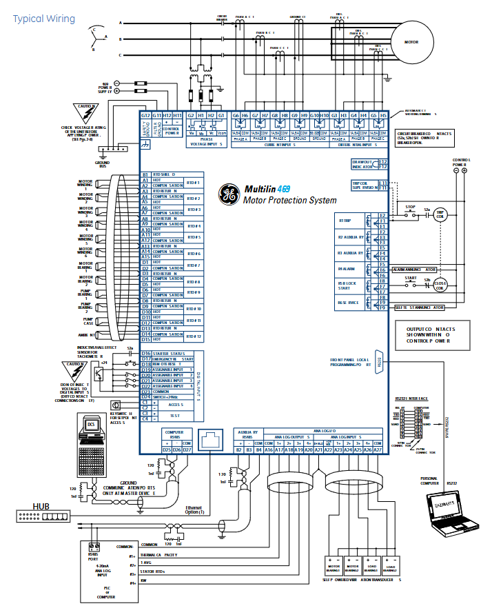
Digital input: 9-way optically isolated input (5 pre-defined: starter status, emergency restart, remote reset, parameter access, test switch; 4 assignable: remote trip/alarm, speed switch, vibration switch, pressure switch, etc.), supports dry contact or NPN collector input.
Analog input/output: 4-channel configurable analog input (supports 4-20mA/0-20mA/0-1mA, input impedance 226 Ω± 10%), 4-channel configurable analog output (specify 4-20mA or 0-1mA when ordering, accuracy ± 1% of full scale, 4-20mA maximum load 1200 Ω, 0-1mA maximum load 10k Ω).
Output relays: 6 sets of Form-C output relays (4 sets of non fault safe type, can be assigned with trip/alarm function; 1 set of non fault safe type start interlock relay; 1 set of fault safe type service relay, indicating loss of control power or internal fault), supporting interlock function, with a maximum rated contact value of 10A continuous (DC 30V 300W, AC 250V 2770VA).
(2) Human Computer Interaction and Communication
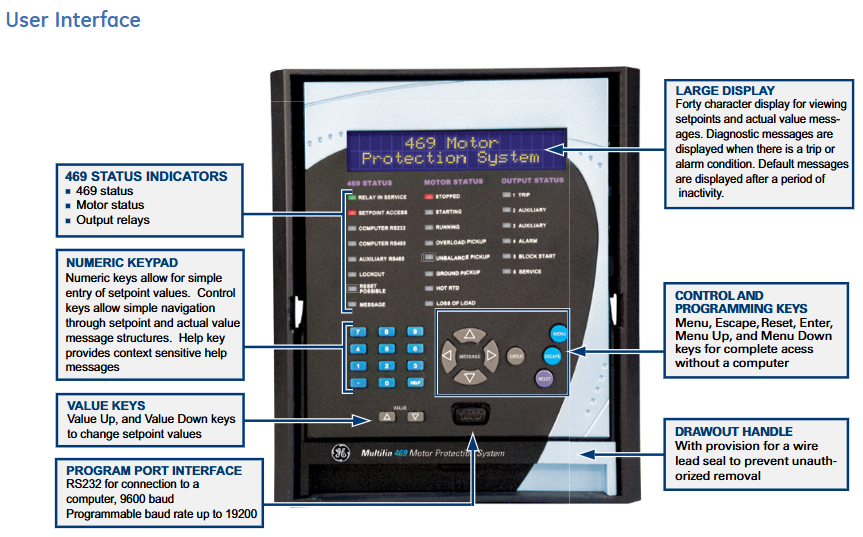
Local interaction: 40 character display screen (displaying parameters, actual values, fault/alarm information), numeric keypad (parameter input and navigation), 22 LED indicator lights (system status, motor status, output relay status), supporting 20 user-defined default messages.
Communication capability: Comes standard with 3 serial ports (front RS232 for debugging, rear 2 RS485 for remote communication), optional 10BaseT Ethernet and DeviceNet ports; Supports Modbus RTU (serial port) and Modbus TCP/IP (Ethernet port), multiple ports can communicate simultaneously, and Ethernet can be connected to local/wide area networks, replacing multi drop wired networks and reducing operation and maintenance costs.
Software and Operations Support
(1) EnerVista software suite
Configuration and Debugging Tools: Provides automatic configuration of motor parameters, firmware upgrades, parameter backup/recovery functions, supports waveform and event viewing, and simplifies fault diagnosis.
Monitoring and integration tools: Viewpoint Monitoring provides plug and play device monitoring, single line diagram monitoring and control, alarm annunitor, trend reports; EnerVista integrator includes OPC/DDE servers, Multilin drivers, and supports seamless integration with existing HMI/SCADA systems.
Maintenance tool: Viewpoint Maintenance provides parameter audit tracking reports, equipment health reports, and comprehensive fault diagnosis to enhance operational security and efficiency.
(2) Pull out structure and retrofit support
Pull out design: easy to replace quickly, reduces downtime, supports wire lead sealing to prevent unauthorized removal.
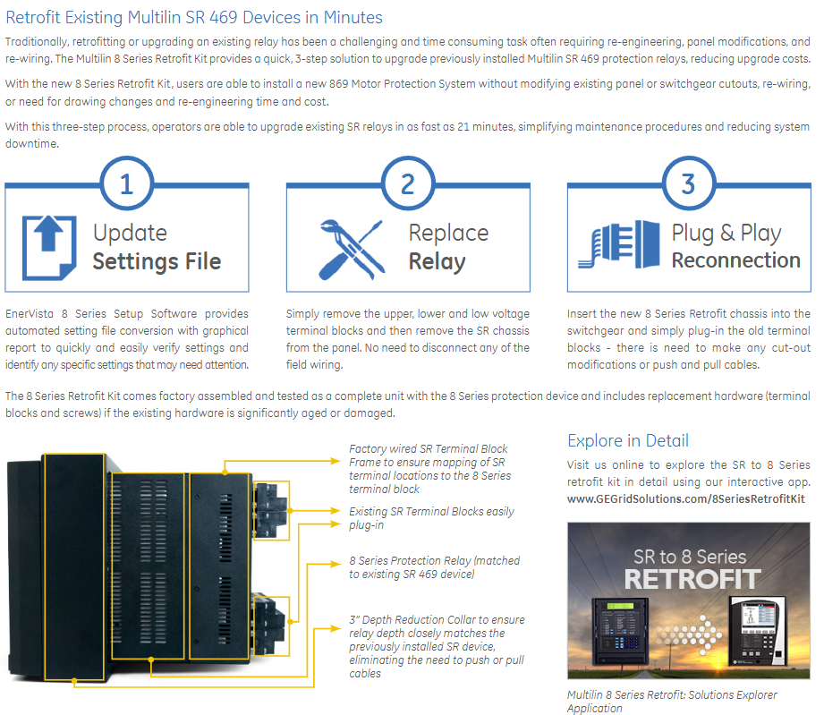
Retrofit upgrade: With the 8 series Retrofit kit, old SR 469 relays can be upgraded to 869 motor protection systems without modifying existing panel openings, rewiring, or changing drawings. The upgrade process only requires 3 steps (updating parameter files, removing old relays, plug-in reconnection) and can be completed in as fast as 21 minutes, reducing upgrade costs and system downtime.
Technical specifications and environmental adaptability
(1) Key technical parameters
Category specification details
Current measurement CT primary side 1-5000A, secondary side 1A/5A; Accuracy: ± 0.5% for current<2 times CT, ± 1% for current>2 times CT
Voltage measurement VT ratio 1.00-15.00:1, secondary side full range 273V AC; Accuracy ± 0.5% of full scale
RTD measurement supports 4 types of RTD, with a range of -50~250 ℃ and an accuracy of ± 2 ℃. Each channel has a 3-level threshold (alarm/high alarm/trip)
Communication speed serial port baud rate 300-19200 bps, Ethernet 10Mbps
Low range of power supply: DC 24-60V/AC 20-48V; High range: DC 90-300V/AC 70-265V, power 45VA (maximum)
(2) Environment and Compliance
Environmental adaptability: working temperature -40~+60 ℃, storage/transportation temperature -40~+80 ℃, humidity 0-95% (55 ℃ without condensation), protection level IP40 (front)/IP20 (back), pollution level 2.
Compliance certification: Compliant with EN60255 series, IEC 61000 series, UL508/UL1053, cULus and other standards, passed ISO9001 quality system certification, CE certification (EN60255-5/27, EN61010-1, etc.).
Ordering and configuration options
(1) Basic models and core options
Basic unit: The model starts with "469", and subsequent codes distinguish key configurations:
CT secondary side: P1 (1A), P5 (5A);
Control power supply: LO (low range: DC24-60V/AC20-48V), HI (high range: DC90-300V/AC70-265V);
Analog output: A1 (0-1mA), A20 (4-20mA);
Extended functions: D (DeviceNet), E (Enhanced Front Panel), T (Enhanced Front Panel+Ethernet), H (Anti harsh Environment Coating).
(2) Optional accessories
Including pull-out handle (with lead seal), RTD sensor, CT/VT of different specifications, Retrofit upgrade kit (including terminal block and depth reduction ring compatible with old SR relays), EnerVista software kit, etc., can be flexibly selected according to on-site needs.
- OMRON
- ABB
- General Electric
- EMERSON
- Honeywell
- HIMA
- ALSTOM
- Rolls-Royce
- MOTOROLA
- Rockwell
- Siemens
- Woodward
- YOKOGAWA
- FOXBORO
- KOLLMORGEN
- MOOG
- KB
- YAMAHA
- BENDER
- TEKTRONIX
- Westinghouse
- AMAT
- AB
- XYCOM
- Yaskawa
- B&R
- Schneider
- KONGSBERG
- NI
- WATLOW
- ProSoft
- SEW
- ADVANCED
- Reliance
- TRICONEX
- METSO
- MAN
- Advantest
- STUDER
- DANAHER MOTION
- Bently
- Galil
- EATON
- MOLEX
- DEIF
- B&W
- ZYGO
- Aerotech
- DANFOSS
- Beijer
- Moxa
- Rexroth
- Johnson
- WAGO
- TOSHIBA
- BMCM
- SMC
- HITACHI
- HIRSCHMANN
- Application field
- XP POWER
- CTI
- TRICON
- STOBER
- Thinklogical
- Horner Automation
- Meggitt
- Fanuc
- Baldor
- SHINKAWA
- Other Brands
- UniOP
- KUKA
- Iba
- Beckhoff
- ADLINK
-
 Atlas Copco PF3000-C-HW Tensor S4 S7 RBU Controller
 -
 Atlas Copco PPBE0613 24VAC Control Panel
 -
Atlas Copco PF3000-C-HW Tensor S4 S7 Controller
-
 Atlas Copco Neos ARC-D130-S+ Inverter Drive
 -
 Atlas Copco Power Focus SL PF4002-G-HW Controller
 -
 Atlas Copco 8436 6770 00 ILT Base Station
 -
 Atlas Copco 1900520400 Air Compressor Control Panel
 -
 Atlas Copco 1900-0711-51 Display Keypad Unit
 -
 Atlas Copco 1900-0710-52 Communication Control Board
 -
 Atlas Copco 1900-0701-04 Control Interface Module
 -
 Atlas Copco 8092 1143 40 SRTT Transducer 180Nm
 -
 Atlas Copco MT Focus 6000 Controller with Pump and Screwdriver
 -
 Atlas Copco Elektronikon GraphicPlus Controller PPBE0622 PPBE0633
 -
 Atlas Copco PF3109-G-DN-HW Tensor 8-9 Power Focus Nutrunner Control
 -
 Atlas Copco Elektronikon P1900520440 Touch Controller
 -
 Atlas Copco Power Focus 8 Controller 8436280002
 -
 Atlas Copco 8436 1500 03 FlexCarrier 3-Slot Torque System Component
 -
 Atlas Copco Power Focus 6000 PF6000 Industrial Controller
 -
 Atlas Copco TC-4000-P-PB-ES Power Macs Controller
 -
 Atlas Copco 8433-0015-20 8433001520 Cable Assembly
 -
 Atlas Copco 49X10301AB Pressure Transducer Sensor
 -
 Atlas Copco 8436180002 Replacement Filter Element
 -
 Atlas Copco C4700A01V216 Compressor Control Module
 -
 Alcatel-Lucent 3HE01019AAAA01 High-Speed Interface Module
 -
 Alcatel-Lucent 111381 Power Distribution Module
 -
 Alcatel TN 2523 1:1 CDN III Module – MRPQAE3
 -
 Alcatel-Lucent 3he06151aaac01 8-Port Interface Module – IPUIBKB3AA
 -
 Alcatel-Lucent LNW46 DMX Metro OC12 Interface Module – 108694878
 -
 Alcatel-Lucent 41A12C FT-2000 Optical Transponder Unit – 108188053
 -
 Alcatel-Lucent 8DG02607AA POW100 DC-DC Converter Module
 -
 Alcatel-Lucent LambdaXtreme WWBQ21 40G Optical Transponder
 -
 Alcatel-Lucent TN1891 5ESS Protocol Handler PHV5 Commcode 108747064
 -
 Alcatel-Lucent 300-0303-900 T1D3PDL1AE Digital Matrix Card
 -
 Alcatel-Lucent G-821M-A Module
 -
 Alcatel Lucent MPT-GC Eth 1G+ARM TX 81-86GHz 3DB80005AAAAO1
 -
 Nokia 3KC48990AB 1830PSS 16FAN2 Fan Unit
 -
 Alcatel 3EC17041AA PSPC-G4 PCB CP011200552
 -
 Alcatel 300-0437-906 Rev F DEXCS DMC T1D1L0S Module
 -
 Alcatel-Lucent 3DW03697ABBA01 TFD64A Module
 -
 Alcatel-Lucent AWR12 S1-1 UN Interface T3PQAC3AAA
 -
 ALCATEL LUCENT 9500-MPR ODU RADIO MPT-HC V2 9558HC 3DB20914BAAA03 6GHZ
 -
 Alcatel-Lucent 9500-MPR ODU 300 11GHz Microwave Radio MPT 3DB23035AEAA01
 -
 Alcatel 2C7-1005-000 Teflon Bell Jar Holder Ring – 146111
 -
 Alcatel-Lucent BNJ118 S1:4 Circuit Board – Interface Module
 -
Alcatel-Lucent 9500-MPR ODU 300 6GHz Microwave Radio MPT 3DB23215AFAA01
-
 Alcatel 3EM04001AA Signal Processing Unit with Accessory Cards
 -
 Alcatel VAUCAL5KAB AA1418FE2BG 3FE67437AAD02 Interface Card
 -
Alcatel-Lucent 1642 Edge Multiplexer N1217P YF – Access Node
-
 Alcatel-Lucent 3HE07158BA 7750 SR-12 12-Port 10GIGE MultiCore IMM IPUCA741AA
 -
 Alcatel 101200429000 Power Divider 746-776 MHz with Heatsinks
 -
 Alcatel-Lucent 9500-MPR ODU 300 MPT 6GHz 3DB23215ADAA01 High Power Radio
 -
 Alcatel-Lucent 9500-MPR MPT-HC 23GHz 2/2P ODU Radio 3DB20474BA
 -
Alcatel-Lucent 9500-MPR ODU 300 MPT 6GHz 3DB23215AAAA01 Low Power Radio
-
Alcatel 3BA52126ABAA OmniPCX 4400 Compact Cabinet
-
 Alcatel-Lucent 3HE12300AA 7750 SR-1 Subrack with Licenses
 -
Alcatel 300-1368-903 Rev C DEXCS SPA-1 T1PQAC1 Line Card
-
 Alcatel-Lucent 408977981 WOWUAB6HAA 10G XPR OTU2 XPonder Card
 -
 Alcatel-Lucent-Nokia 3HE08423AARC01 7750 SR Control Processor Module IPUCBGZ1AA
 -
 Alcatel-Lucent 9500-MPR ODU 300 MPT 6GHz 3DB23215ABAA01 Low Power Radio
 -
 Alcatel-Lucent CPU7-2 3BA23259ABJE 05 Control Processor Module
 -
 Alcatel WTM11AD 3DW03915DABA01 Optical Transponder Module
 -
Alcatel-Lucent 1340FMPK Card Chip BA5IVY6BAA – Processor Module
-
 Alcatel-Lucent 3HE06151ACAC01 Control Fabric Module
 -
 Alcatel-Lucent 9500-MPR 18GHz 1P-1 Protection ODU Radio 3DB20433BA AA04
 -
 Alcatel-Lucent 9500-MPR ODU MPT-HC 18GHz Radio 3DB20433BAAA04
 -
 Alcatel-Lucent SM269 LMPQ04KAXX Circuit Pack – Interface Module
 -
 Alcatel OME25HP Filter Cartridge – 107494
 -
Alcatel-Lucent ALU-BZ74 99BC-4 –48V Battery Cabinet
-
 Alcatel-Lucent WWAA37 Optical Amplifier WMAPZNZAAB – CP Series
 -
ALCATEL LUCENT 9500-MPR ODU RADIO MPT-HC V2 9558HC MPT-XP 3DB20476BAAA04 23GHZ
-
 Alcatel Tyco Yukon ES760A Rectifier
 -
Alcatel-Lucent 9500-MPR ODU 300 MPT 23GHz 3DB23045HMAA02 Microwave Radio
-
Alcatel-Lucent 9500-MPR ODU MPT-HC 11GHz 3DB20548ACAA01 Microwave Radio
-
 Alcatel Lucent 3DH03173AKAA Module
 -
Alcatel-Lucent 76-0300-02 CSM-V2 PCB
-
 Alcatel 9400 UX ODU Module 3CC06729ABAA
 -
 Alcatel-Lucent 408981363 Jigsaw A Band Block 24/-48V KS24624L58
 -
 Alcatel 3BA53095 PCB Card
 -
 Alcatel 2C7-1005-000 Bell Jar Holder Ring Teflon PC7-1005-000
 -
 Alcatel-Lucent ES640 PWDQAGKUAA 5ESS 48V DC Alarm Control Unit
 -
 Alcatel-Lucent 9500-MPR ODU 300 23GHz Microwave Radio MPT 3DB23045HM
 -
Alcatel-Lucent KFA720 WMOTCMVLAB Optical System Interface Carrier
-
Alcatel-Lucent 9500-MPR ODU MPT-HC V2 15GHz Microwave Radio 3DB20373BAAB04
-
 Alcatel-Lucent AKM70 S1-7 SMUX1 Sub-Multiplexer – T3PQWAEAAH
 -
 Alcatel-Lucent 107486490 DDM-2000 SONET DS3 Circuit Pack – BBG4B
 -
 Alcatel-Lucent SBEVM BNJ82 1:12 Module – AV950-01168
 -
 Alcatel-Lucent 938A Optical Loss Set – Test & Measurement Kit
 -
Alcatel-Lucent MS1025-25O16-ED Fiber Optic Unit – 48VDC
-
Alcatel-Lucent 9500-MPR ODU MPT-HC 23GHz 1/1P Microwave Radio 3DB20473BA AA04
-
Alcatel-Lucent bCEM-U Control Module – 3BK28676ABAC01
-
 Alcatel ASI20 Detector Control Module
 -
 Alcatel Lucent 130B S-1 PWPQ08B Power Unit
 -
 Alcatel-Lucent 9500-MPR ODU MPT-HC V2 9558HC 6GHz 3DB20441BBAA02
 -
Alcatel-Lucent 9500-MPR ODU MPT-MC 15GHz 3DB20824AAAA02 Microwave Radio
-
Alcatel-Lucent 9500-MPR ODU MPT-MC 15GHz 3DB20822AAAB02 Microwave Radio
-
 Alcatel-Lucent 3AL92111AA 1P10GSO Interface Module
 -
 Alcatel 8220 CTT 450 Turbo Pump Controller 127821
 -
 Alcatel-Lucent 3AL78823AAAE 02 Module
 -
 Alcatel-Lucent 90-0413-01 Universal Card
 -
Alcatel-Lucent BRMA 10Base-T/100Base-TX Connecting Box 3BA56170ACAB010842
-
 Woodward Micronet 5453-279 Rev E Chassis Rack for TMR Control
 -
 Alcatel-Lucent KFA632 WMOTBUKLAA 10G Optical Interface Carrier
 -
Alcatel-Lucent 9500-MPR ODU MPT-HC V2 3DB20474BAAB04 23GHz Microwave Radio
-
 Alcatel-Lucent KFA720 WMOTCMVLAB SFP/XFP Optical Interface Carrier
 -
Alcatel-Lucent 3AL00114AB Universal Interface Module
-
 Alcatel-Lucent BBG9 S1:1 OHCTL Optical Hardware Control Module
 -
Alcatel-Lucent FB16401-A-I03 GTD-5 Analog Master/Slave Control Board
-
 Alcatel-Lucent MCR1721B Control Module
 -
Alcatel-Lucent 9500-MPR 3DB20547ACAA01 ODU MPT-HC 11GHz Microwave Radio
-
 Alcatel-Lucent 3HE01014AAAA02 Interface Module
 -
 Alcatel-Lucent 244-2091-005 High Density Digital Line Card V1.5
 -
 Alcatel-Lucent LAMBDAXTREME WWAA36 Optical Amplifier Module
 -
Alcatel-Lucent 9500-MPR ODU MPT-HC 6GHz 2P-2 Radio 3DB20444BAAA05
-
Alcatel-Lucent 9500-MPR ODU MPT-HC V2 9558HC MPT-XP 6GHz 3DB20442BBAA02
-
Alcatel-Lucent 9500-MPR ODU MPT-HC 23GHz 3DB20476ABAA01 Microwave Radio
-
 Alcatel Lucent 3HE01019AAAA01 Module
 -
 Alcatel CPU5 3BA23071 PCB Card with IO2 3BA23050 Set
 -
Alcatel-Lucent 9500-MPR ODU MPT-HC V2 9558HC 6GHz 3DB20443BBAA02
-
 Alcatel Lucent 500-1113-211 Rev H Channel Bank Assembly
 -
Alcatel Lucent 89-0419-B-2 BA9ATS0FAB Frontal Compute Module
-
Alcatel-Lucent LambdaXtreme 1625 WWAF31 Optical Amplifier CP Module
-
Alcatel Z24 3BA53065 Analog Extension Card 3BA52065 AAAA KAZZB-01
-
 Alcatel 3EH08263AAXX000448 OmniPCX Office Large PBX System
 -
 Alcatel Lucent VSEM-C 3FE62453 XA VAUCAJZKAA 7330 DSLAM Line Card
 -
Alcatel-Lucent 9500-MPR ODU MPT-HC 3DB20432BAAA04 18GHz Microwave Radio
-
Alcatel-Lucent 9500-MPR ODU MPT-HC 3DB20546ACAA01 11GHz Microwave Radio
-
 Alcatel-Lucent 3DB04823AAAA Circuit Board
 -
 Alcatel-Lucent 3DB04530AAAA Circuit Board


