Honeywell System 57 5704 Control System
Honeywell System 57 5704 Control System
Product positioning and core functions
The Honeywell System 57 5704 control system is a microprocessor controlled device used for industrial gas detection, belonging to the System 57 product family. Its core function is to monitor industrial gas detectors installed on site, achieve multi-channel gas concentration monitoring, alarm triggering, and system management. It is suitable for indoor non hazardous areas and should not be exposed to rainwater or moisture. It is also not designed for use in hazardous areas. The system supports catalytic and 4-20mA input types of gas sensors, with flexible alarm configuration, remote control, and self diagnostic capabilities. Calibration, maintenance, and parameter settings can be performed through engineering cards, and it is also compatible with extended functions such as Modbus communication and event printing.
System composition and hardware specifications
(1) Core hardware module
Four Channel Control Card
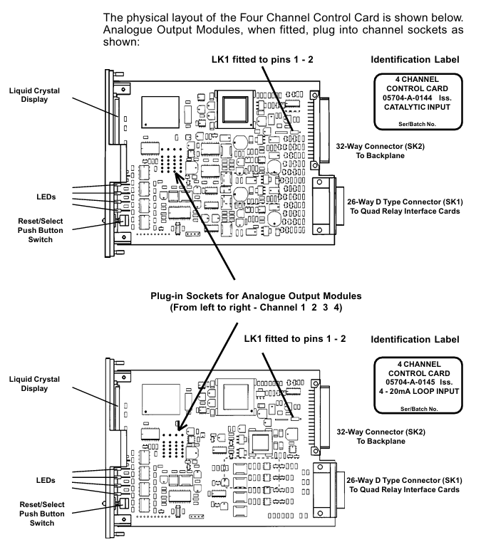
Type differentiation: divided into catalytic input type (model 05704-A-0144) and 4-20mA input type (model 05704-A-0145). The former supports catalytic gas sensors and provides constant current drive (adjustable from 90-315mA), while the latter is suitable for 4-20mA circuit power supply sensors with a measurement range of 0-25mA.
Display and indication: Equipped with four LCD displays (25 segment analog bar, 4-digit digital display, 4-digit message display, icon area), 4 channel LEDs (CHL1-CHL4) and 1 Attention (ATTN) LED, which can distinguish A1/A2/A3 alarm, STEL/LTEL alarm, fault, suppression and other states by LED flashing frequency/color.
Core parameters: Initial accuracy ± 1%, alarm set point resolution 1% of full range, electronic drift<± 3%/6 months, operating voltage 18-32V DC, catalytic type maximum power consumption 12.8W, 4-20mA type maximum power consumption 8.3W.
relay interface module
Quad Relay Interface Card (model 05704-A-0121): Provides 4 Single Pole Double Throw (SPCO) relays, supporting latch/non latch, power on/off action modes, and rated relay contacts 5A@110 /250V AC or 32V DC, supporting interface connection between sensors and control cards, with a maximum power consumption of 1.7W.
Relay Interface Assembly (model 05704-A-0131): It consists of four relay interface cards and an extended relay card, including 12 SPCO relays and 4 Single Pole Single Throw (SPST) relays, occupying 2 card slots, with a maximum power consumption of 6.5W, suitable for scenarios that require more relay outputs.
Engineering Card (Model 05701-A-0361)
Functional positioning: The core module for system configuration, calibration, and maintenance, equipped with green power LED, red unlock LED, as well as directional keys (up/down), confirm/cancel keys, function keys (BEAD mA, ALARMS, ZERO, SPAN, etc.).
Core Capability: Supports sensor bridge current regulation, alarm threshold setting and relay testing, zero/range calibration, system clock setting, can be configured and data printed through RS232 interface connected to printer or PC, with a power consumption of approximately 1.5W.
DC Input Card (Model 05701-A-0325)
Function: Provides a system DC power supply interface, supports two independent power inputs (such as main power and backup battery), has diode isolation and 10A anti surge fuse, supports 2.5mm ² (14 AWG) wire terminals, and operates at a voltage of 18-32V DC.
other modules
Analog output module: divided into current absorption type (04200-A-0145) and current source type (04200-A-0146), output range 0-20mA or 4-20mA software optional, linearity ± 2% of full range, supporting external power supply of 18-40V.
Expansion module: including event printing module (05701-A-0314), Modbus interface module (RS232 type 05701-A-0313, RS485/422 type 05701-A-0312), alarm update module (05701-A-0309), etc., used to expand communication and alarm functions.
(2) System rack and cabinet
Rack: available in full 19 inch and half 19 inch widths, supporting front or rear wiring, including engineering cards, DC input cards, and interconnecting cables (front wiring type), made of galvanized steel, with M5 grounding terminal bolts, weighing approximately 287.6-217.6g including modules (depending on model).
Cabinet: divided into 8 channels (model 05701-A-0452) and 16 channels (model 05701-A-0451), made of low carbon steel, RAL 7015 dark gray, equipped with knockout cable sealing sleeves (8 channels include 2 M25, 8 M20, etc.), weighing 10kg for 8 channels and 13.5kg for 16 channels.
(3) Power supply unit
AC-DC power supply unit: divided into 8 channels (model 05701-A-0406) and 16 channels (model 05701-A-0405), input 85-264V AC (47-440Hz) or 110-340V DC, output 24V DC ± 10%, can be upgraded by adding a 50W switch module (model 05701-A-0440) (maximum 100W for 8 channels, maximum 200W for 16 channels), with overload protection (triggered by 105% rated load, automatic recovery), maximum leakage current 0.75mA/50W module.

Installation and wiring requirements
(1) Environment and Location
For indoor use only, avoid heat sources, moisture, and physical damage. The ambient temperature is -5-55 ℃ (ATEX certification system is 0-55 ℃), the humidity is 0-90% RH (no condensation), and the altitude is ≤ 2000m.
- ABB
- General Electric
- EMERSON
- Honeywell
- HIMA
- ALSTOM
- Rolls-Royce
- MOTOROLA
- Rockwell
- Siemens
- Woodward
- YOKOGAWA
- FOXBORO
- KOLLMORGEN
- MOOG
- KB
- YAMAHA
- BENDER
- TEKTRONIX
- Westinghouse
- AMAT
- AB
- XYCOM
- Yaskawa
- B&R
- Schneider
- Kongsberg
- NI
- WATLOW
- ProSoft
- SEW
- ADVANCED
- Reliance
- TRICONEX
- METSO
- MAN
- Advantest
- STUDER
- KONGSBERG
- DANAHER MOTION
- Bently
- Galil
- EATON
- MOLEX
- DEIF
- B&W
- ZYGO
- Aerotech
- DANFOSS
- Beijer
- Moxa
- Rexroth
- Johnson
- WAGO
- TOSHIBA
- BMCM
- SMC
- HITACHI
- HIRSCHMANN
- Application field
- XP POWER
- CTI
- TRICON
- STOBER
- Thinklogical
- Horner Automation
- Meggitt
- Fanuc
- Baldor
- SHINKAWA
- Other Brands


