
How to use Honeywell OELD intelligent junction box
Provide local visual status indication and Bluetooth low-energy interface, which can be configured and maintained through Bluetooth enabled mobile devices, certified by ATEX and IECEx, suitable for Zone 1 (gas) or Zone 21 (dust) hazardous areas, and the explosion-proof version also has cULus certification, suitable for Class I Zone 1 or Class II Zone 1.
There are 5 entrances (M25 or 3/4 "NPT depending on the version) and 3 certified plugs, while the Ex e version of the OELD only has 5 M25x1.5 entrances.
The increased safety (Ex e) version uses terminal blocks of specific manufacturers and types, while the explosion-proof (Ex d) version is black and the increased safety version is green. They must not be mixed, otherwise the product certification will be invalidated.
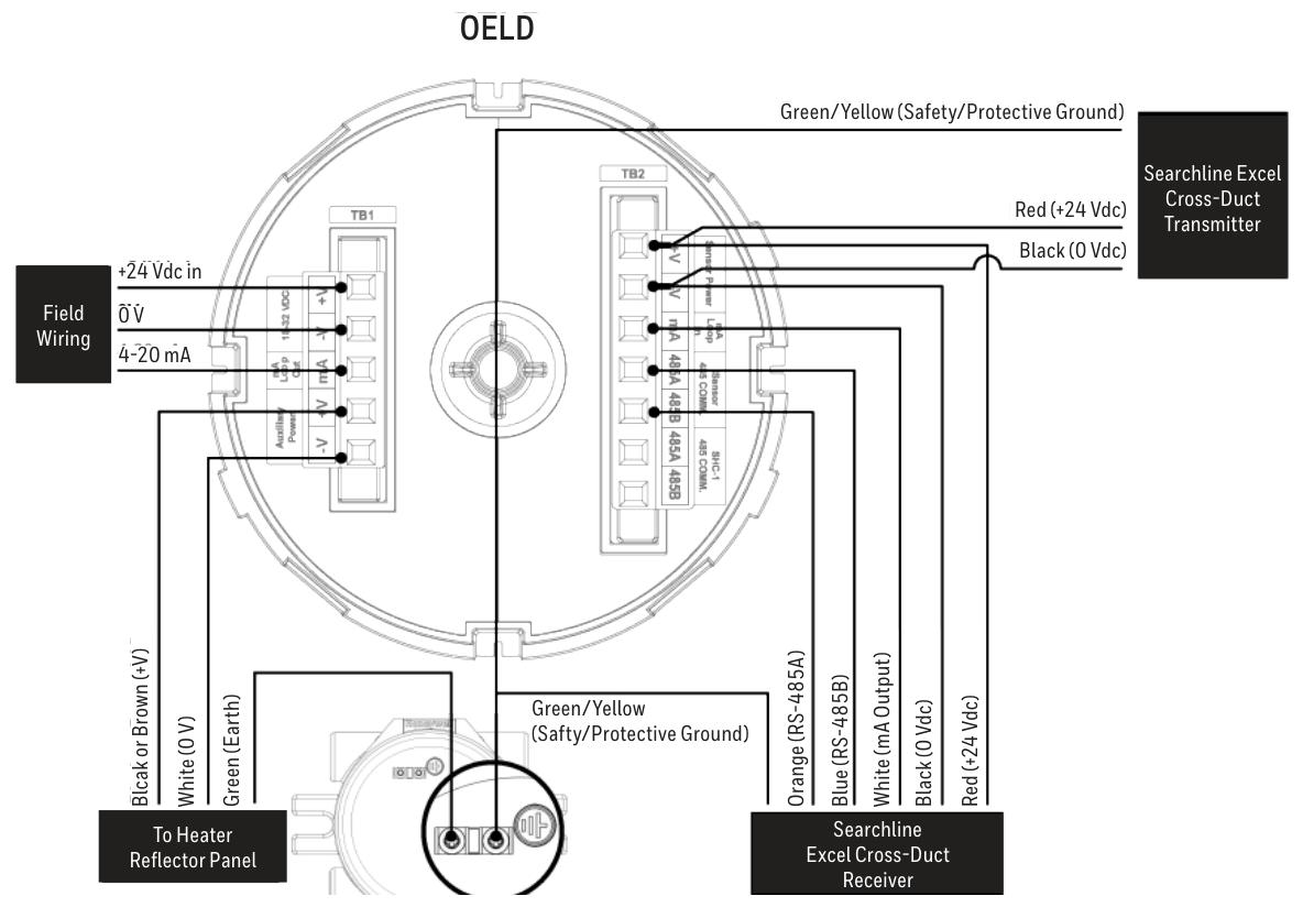
Wiring diagram
Provided OELD and Searchpoint Optima Plus、Searchline Excel、Searchline Excel Cross-Duct(XD) Wait for the wiring diagram of the detector, as well as the connection method of the detector with the current sink and current source configuration.
Grounding connections should avoid grounding loops. The OELD has two internal grounding points, and the on-site cable shielding layer should be connected to the instrument grounding in the control room. The internal and external grounding points of the OELD have corresponding specifications and connection requirements.
Power supply and cables
The OELD requires a voltage supply of 18-32Vdc (nominal 24Vdc) with a maximum power consumption of 2W, taking into account the voltage drop caused by cable resistance to ensure the minimum required supply voltage at the detector.
The cable should be suitable for hazardous area classification and comply with relevant regulations. It is recommended to use industrial grade shielded field cables. The allowable wire size for terminals is 0.2-2.5mm ² (24-12AWG), and the rated wire temperature should be greater than 80 ° C. The terminal tightening torque should be 0.5Nm to 0.6Nm.
Configuration
Configurable parameters
Including local alarm indication threshold (can be set between 5 and 65% FSD, default 20% FSD), mA input level setting (to match the detector's mA output curve), and OELD universal display settings (such as full-scale range, measurement unit, gas name, etc.).
configuration process
Configure by running the OELD App on a mobile device, including steps such as launching the application, logging in, searching for nearby OELD units, selecting and confirming connections, etc.
After completing the configuration or changing the settings, the configuration should be read back and verified to ensure that the changes are correct.
Operation
Startup and self-test
The startup and self-test sequence takes about 60 seconds, during which display testing, backlight testing, internal hardware and memory checks, etc. will be performed. After completion, it will enter normal operating mode.
normal operation
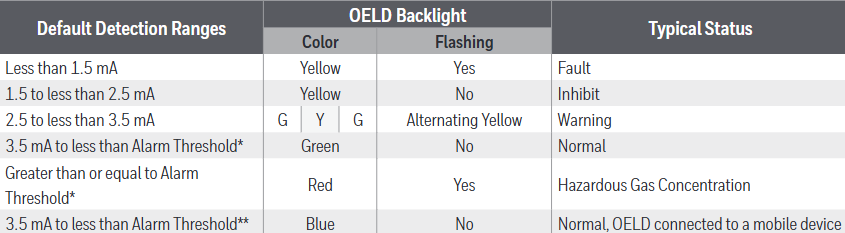
During normal operation, the LCD backlight indicates the detector status based on the 4-20mA output of the detector, and different current ranges correspond to different backlight colors and flashing states.
The display screen displays gas concentration information (in graphical and numerical form) and other information during normal operation. At low temperatures, the refresh rate of the display screen will automatically decrease. At extremely low temperatures, the screen clarity may decrease, but it can return to normal after the temperature is restored.
communication model
Equipped with Bluetooth Low Energy (BLE) interface, it supports non-invasive connection with mobile devices running the OELD App, and can also communicate with specific detectors through RS-485 interface.
Honeywell Analytics SHC-1 handheld interrogator and SHC protection device can also be used to connect with relevant detectors, but attention should be paid to relevant warnings and precautions.
OELD Mobile Application
Installation and operation
The OELD mobile application can run on Android 4.3 (Jelly Bean) or higher operating systems that support Bluetooth Low Energy (BLE) and can be downloaded and installed from the Google Play Store.
The first launch requires reading the End User License Agreement, logging in or registering an account. Registration requires an Internet connection and at least one OELD device's QR code.
Connection and Configuration
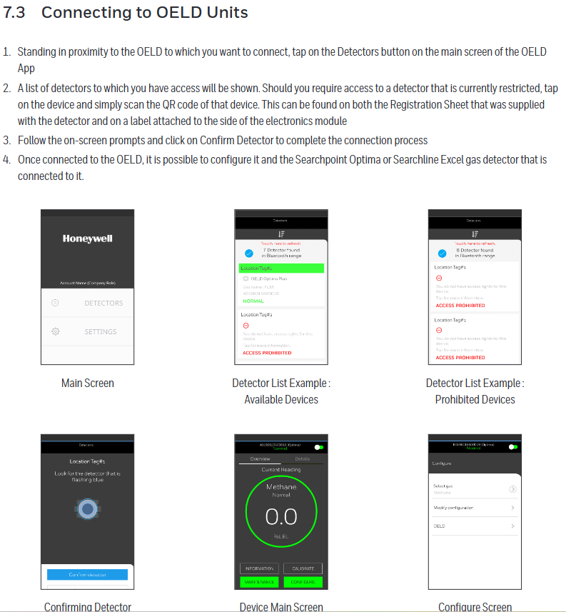
Can connect to OELD devices that have already been registered to the user account. The connection steps include clicking on relevant buttons on the main screen of the application, selecting the device, scanning the QR code (if access to restricted devices is required), confirming the connection, etc.
Multiple parameters of the OELD device can be configured, as well as parameters of detectors such as Searchpoint Optima Plus and Searchline Excel connected to the OELD, and calibration operations can also be performed (specific detectors).
Maintenance and troubleshooting
maintenance
Regularly inspect the OELD and cables for physical damage, clean the glass windows with a damp cloth, and do not use solvents or abrasive cleaners. The OELD has no user repairable parts.
It is recommended to check the configuration and operation of the equipment at least once a year, and the gas detector connected to the OELD should be checked and calibrated according to its operating instructions.
The replacement of the display module requires following specific steps, including power-off, removing the cover and electronic module, replacing the module, etc. After replacement, it needs to be reconfigured.
Malfunctions and warnings
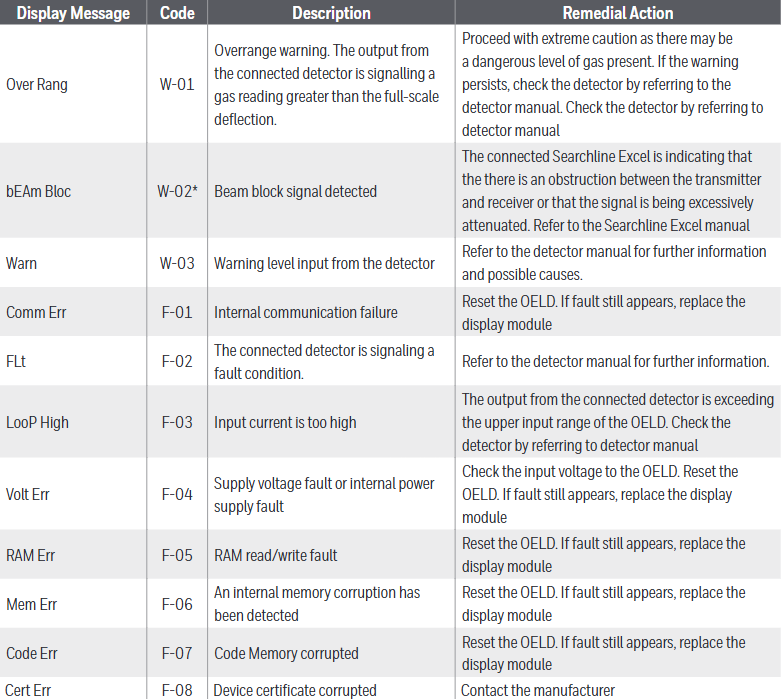
Different display messages and codes correspond to different types of faults or warnings, such as "Over Rang" (W-01) indicating an over range warning, "Comm Err" (F-01) indicating an internal communication fault, etc., with corresponding remedial measures.
- OMRON
- ABB
- General Electric
- EMERSON
- Honeywell
- HIMA
- ALSTOM
- Rolls-Royce
- MOTOROLA
- Rockwell
- Siemens
- Woodward
- YOKOGAWA
- FOXBORO
- KOLLMORGEN
- MOOG
- KB
- YAMAHA
- BENDER
- TEKTRONIX
- Westinghouse
- AMAT
- AB
- XYCOM
- Yaskawa
- B&R
- Schneider
- KONGSBERG
- NI
- WATLOW
- ProSoft
- SEW
- ADVANCED
- Reliance
- TRICONEX
- METSO
- MAN
- Advantest
- STUDER
- DANAHER MOTION
- Bently
- Galil
- EATON
- MOLEX
- DEIF
- B&W
- ZYGO
- Aerotech
- DANFOSS
- Beijer
- Moxa
- Rexroth
- Johnson
- WAGO
- TOSHIBA
- BMCM
- SMC
- HITACHI
- HIRSCHMANN
- Application field
- XP POWER
- CTI
- TRICON
- STOBER
- Thinklogical
- Horner Automation
- Meggitt
- Fanuc
- Baldor
- SHINKAWA
- Other Brands
- UniOP
- KUKA
- Iba
- Beckhoff
- ADLINK
-
 National Instruments PCI-6250 Multifunction DAQ Device
-
 National Instruments PCI-6224 Multifunction DAQ Card
-
 National Instruments cRIO-9081 CompactRIO Controller
-
 National Instruments USB-6353 X Series DAQ Device
-
 National Instruments NI-9223 Simultaneous Analog Input Module
-
 National Instruments PXIe-8133 Embedded Controller
-
 National Instruments NI-9403 Digital I/O Module
-
 National Instruments PCI-6111E Multifunction I/O Card
-
 National Instruments FP-1001 FieldPoint Network Module
-
 National Instruments PCI-6517 Industrial Digital I/O Card
-
 National Instruments USB-5680 Power Meter
-
 National Instruments PXI-6562 Digital Module
-
 National Instruments PCI-6254 DAQ Card
-
 National Instruments NI 9266 Output Module
-
National Instruments NI 9862 CAN Module
-
 National Instruments NI 9217 Input Module
-
National Instruments PCI-4472 DSA Card
-
 National Instruments NI 9232 Vibration Module
-
 National Instruments NI-9269 Output Module
-
 National Instruments GPIB-120B Interface
-
 National Instruments NI 9209 Input Module
-
National Instruments NI 9210 Input Module
-
 National Instruments NI 9381 Module
-
National Instruments PXI-2570 Relay Module
-
 National Instruments 777318140 Cable
-
 National Instruments 781049-01 Module
-
 National Instruments 779140-01 Module
-
 National Instruments PXI-6115 DAQ Card
-
 National Instruments cDAQ-9185 Chassis
-
National Instruments NI-9375 I O Module
-
National Instruments USB-6366 X Series DAQ Device
-
 National Instruments USB-6361 X Series DAQ Device
-
 National Instruments PXI-4496 Sound and Vibration Module
-
 National Instruments PCI-6289 Multifunction DAQ Card
-
 National Instruments PXI-8119 Quad-Core Controller
-
National Instruments NI-9206 Analog Input Module
-
National Instruments 779516-01 Ordering Part Number
-
 National Instruments cDAQ-9132 CompactDAQ Controller
-
 National Instruments 782401-01 Ordering Part Number
-
National Instruments PXI-8105 Embedded Controller
-
 National Instruments USB-6361 Multifunction I/O Device
-
 National Instruments SCXI-1314 Terminal Block
-
 National Instruments PCI-6515 Industrial Digital I/O Card
-
National Instruments 779038-01 Ordering Part Number
-
 National Instruments cRIO-9012 CompactRIO Controller
-
 National Instruments PXI-8364 MXI-Express Interface
-
National Instruments PXIe-8360 Interface Card
-
 National Instruments 196859B-01 Ordering Part Number
-
 National Instruments PXIe-1073 5-Slot Chassis
-
 National Instruments NI 9209 Voltage Input Module
-
 National Instruments USB-5133 Digitizer
-
 National Instruments PXI-1044 Chassis
-
National Instruments NI 9266 785046-01 Module
-
 National Instruments USB-6216 DAQ Device
-
National Instruments NI 9266 Output Module
-
National Instruments NI 9230 Vibration Module
-
 National Instruments PCI-6230 DAQ Card
-
National Instruments PXI-6123 DAQ Card
-
National Instruments PCI-6255 DAQ Card
-
 National Instruments PXI-8433 Serial Module
-
 National Instruments PXIe-4138 Source Measure Unit
-
 National Instruments 781044-01 PCIe-6321 DAQ Part Number
-
 National Instruments PXIe-6356 X Series DAQ Module
-
 National Instruments PCI-6513 Industrial Digital Output Card
-
National Instruments 183345A-04 Ordering Part Number
-
 National Instruments PCIe-6351 X Series DAQ Card
-
National Instruments PXI-4070 FlexDMM Module
-
National Instruments PXI-6225 Multifunction DAQ Module
-
 National Instruments 781496-01 Ordering Part Number
-
 National Instruments 779592-01 Ordering Part Number
-
 National Instruments SCXI-1121 Module
-
 National Instruments NI 9148 Chassis
-
National Instruments PXI-6255 DAQ Module
-
 National Instruments USB-4065 DMM
-
 National Instruments PXI-6221 DAQ Module
-
 National Instruments PXIe-1065 Chassis
-
National Instruments NI 9210 Input Module
-
National Instruments 778948-01 Output Module
-
 National Instruments cRIO-9014 Controller
-
National Instruments cDAQ-9171 Chassis
-
 National Instruments USB-6363 DAQ Device
-
National Instruments NI 9467 GPS Module
-
 National Instruments USB-6351 DAQ Device
-
National Instruments NI 6581 Adapter Module
-
 National Instruments 781045-01 Output Module
-
National Instruments PCI-6225 DAQ Card
-
 National Instruments TRC-8543 CAN Cable
-
National Instruments PXIe-1073 Chassis
-
 National Instruments USB-6003 DAQ Device
-
 National Instruments NI 9476 Output Module
-
National Instruments myRIO-1900 Embedded Controller
-
National Instruments NI-9263 Analog Output Module
-
 National Instruments 158561A-01L Ordering Part Number
-
 National Instruments 785024-01 Ordering Part Number
-
National Instruments PCI-6510 Industrial Digital I/O Card
-
 National Instruments USB-6259 Multifunction DAQ Device
-
National Instruments USB-8452 I2C SPI Interface Device
-
 National Instruments PXI-8432 Serial Interface Module
-
National Instruments PXIe-5644R Vector Signal Transceiver
-
 National Instruments PXI-2569 Relay Module
-
National Instruments 781174-01 Module
-
National Instruments 782000-01 Module
-
 National Instruments PXI-5152 Digitizer
-
 National Instruments PXI-6284 DAQ Card
-
National Instruments PCI-1428 Frame Grabber
-
 National Instruments PXI-1050 Chassis
-
National Instruments NI USB-8486 Fieldbus
-
National Instruments NI 9862 CAN Module
-
 National Instruments NI 9146 FPGA Chassis
-
 National Instruments PXI-8108 Controller
-
 National Instruments NI SWB-2816A Matrix Module
-
 National Instruments NI 9269 Analog Output Module
-
National Instruments PCI-6031E Multifunction DAQ Card
-
National Instruments PXI-6713 Analog Output Module
-
National Instruments NI 9216 RTD Input Module
-
National Instruments NI-9237 Strain Bridge Input Module
-
National Instruments PXI-5124 High Resolution Digitizer
-
National Instruments USB-6343 X Series DAQ Device
-
 National Instruments PXIe-6536 Digital I/O Module
-
 National Instruments CAL-4330 Calibration Fixture
-
 National Instruments PXI-4110 Programmable Power Supply
-
 National Instruments 781503-01 Input Module
-
 National Instruments FP-AI-V10 Module
-
National Instruments PXI-5114 Digitizer Card
-
 National Instruments PXIe-8398 MXI Module
-
 National Instruments cRIO-9056 Controller
-
National Instruments PCI-6509 DIO Device
-
 National Instruments cRIO-9053 Controller


