
Omron F160-2 Visual Expert Guide
Omron F160-2 Visual Expert Guide
The core value and applicable scenarios of expert menu
Omron F160-2 Vision Sensor is an embedded system designed for industrial inspection. Its Expert Menu provides 17 measurement methods, covering area, defect, center of gravity, edge, search, character recognition, classification, and almost all common machine vision needs. Compared with simple conversational menus, expert menus allow users to make fine adjustments to measurement areas, binary thresholds, filtering processing, output expressions, etc., making them particularly suitable for applications that require strict customization of detection logic, processing of complex workpieces, or data exchange with PLCs and robots.
This article is based on the F160-2 expert menu operation manual, and from the perspective of engineering practice, it systematically explains the entire process from startup, image adjustment, position compensation, measurement method setting, to data output, scene switching, and fault troubleshooting.
Startup and Basic Operations
2.1 System Startup and Mode Selection
After powering on F160-2, first enter the selection menu screen. Use the directional keys to move the cursor to "Expert Menus" and confirm, then enter the camera settings screen. In this screen, it is necessary to specify the connected camera model (such as F160-S1, F160-S2, etc.) and whether intelligent lighting (LTC20/LTC50) is used. After completing the settings, enter the Basic Screen of the Expert menu.
The expert menu has five operation modes:
SET (Set Mode): Configure detection conditions, including image adjustment, position compensation, measurement area, output expression, and display content.
MON (Monitoring Mode): Measurements are performed under set conditions, and the results are displayed on the screen but not output to external devices for debugging.
RUN (running mode): The measurement is officially executed, and the results are output to external devices through parallel or serial interfaces.
SYS (System Mode): Set camera parameters, communication format, display mode, password, startup conditions, and other system environment settings.
TOOL (tool mode): perform data backup (to computer or memory card), clear stored images, line brightness check, I/O monitoring, etc.
2.2 Menu Tree and Data Input
The expert menu adopts a hierarchical structure. Move the cursor with the directional keys, press the ENT key to enter the next level, and press the ESC key to return to the previous level. Items marked with inverted triangles indicate a multiple-choice list. When entering a numerical value, use the left and right keys to move the cursor to the number of digits to be modified, and use the up and down keys to increase or decrease the value. When entering characters, the software keyboard pops up on the screen, select the character and confirm.
Standard process for setting detection conditions
In SET mode, follow the following seven steps to complete the configuration of a detection task.
3.1 Step 1: Enter the setup mode
Move the cursor to "MON" on the basic screen, press ENT and select "SET" to enter. If the current scene has never been set, the camera mode selection interface (single camera or dual camera Camera 0+1) will appear first. For the F160-S2 camera, you can also set the "Number of input lines". Reducing the number of lines can shorten the image acquisition time, but it will lose some vertical image areas.
3.2 Step 2: Adjust the image
Image adjustment includes shutter speed, intelligent lighting control, filtering processing sequence (position compensation and measurement can be set separately), filtering methods (smoothing, dilation, erosion, median, edge enhancement, vertical/horizontal edge extraction, edge extraction, etc.), and background suppression (BGS).
Shutter speed: Suitable for fast-moving objects to prevent image trailing.
Intelligent lighting: The light intensity of each LED segment can be adjusted in sections (0-7), and there are also 15 preset lighting modes built-in, which can be switched through shortcut keys.
Filtering: For example, smoothing can reduce the interference caused by slight surface irregularities; Edge extraction can enhance contrast and facilitate subsequent edge detection.
Background suppression: Set the upper and lower limits of grayscale, only retaining the grayscale range of interest, and turning the rest into black (0) or white (255).
All these adjustments can be previewed in real-time and can be independently set for position compensation and measurement area.
3.3 Step 3: Position compensation
When the position and angle of the tested workpiece are inconsistent, the position compensation function must be used. F160-2 provides two position compensation regions (1st region and 2nd region), each of which can be measured using one of six methods: centroid and area, centroid and axis angle, label, grayscale search, edge position, and rotation search. The compensation directions can be set separately for X, Y, and θ compensation sources.
A typical compensation strategy is to first perform a coarse compensation on an area with distinct features (such as a circular hole), and then perform a fine compensation on another area to improve stability.
3.4 Step 4: Set the measurement area and measurement method
F160-2 supports up to 32 measurement regions (Regions 0~31), and each region can independently choose a measurement method. The 17 measurement methods provided by the expert menu include:
Area (Variable Box): Suitable for objects with changes in size and position, automatically searches for upper, lower, left, and right edges, and dynamically adjusts the measurement box.
Defect (Variable Box): Similar to area measurement, but used for detecting defects.
Center of gravity and area: The simplest binary measurement of center of gravity/area.
Center of gravity and axial angle: In addition to the center of gravity and area, the equivalent principal axis angle of the ellipse is also calculated.
OCR single character: recognize characters, built-in dictionary, output character codes.
Classification: Pre register multiple models (up to 36 indexes, with a maximum of 5 models per index), and output the index number of the most similar model. The system will automatically generate auxiliary models between registered models to improve stability.
Defect: Detect defects on unpatterned surfaces, measuring areas can be rectangles, circles, arcs, or lines.
Density data: Calculate the average grayscale and deviation within the area.
Edge spacing: Detect a set of edges and output the number of edges, average spacing, maximum/minimum spacing, etc.
Edge position: detects the position of a single edge.
Edge width: Detect a pair of edges and calculate the width.
Grayscale search/precise search: Based on grayscale template matching, precise search supports sub-pixel localization, with higher accuracy but slightly slower speed.
Flexible search: Multiple templates can be registered, suitable for workpieces with inconsistent shapes.
Label: Mark the white area after binarization, which can count the number of labels, specify the area and center of gravity of the labels.
Relative search: Simultaneously detect two templates (reference point and measurement point) and output the relative position between the two.
Rotation search: Search templates within a specified angle range and output rotation angles and positions.
For each method, it is necessary to set a binarization threshold (if binarization is involved), draw the measurement area, set judgment conditions (upper and lower limits), and optional detailed conditions (such as edge level, noise threshold, pixel skipping, etc.).
3.5 Step 5: Set output expression
The expression function allows users to perform arithmetic operations, logical operations, or function calculations on measurement results and output the results to external devices. Expressions can reference the following:
Measurement values: such as R0. X (X coordinate of region 0), R1. AR (area of region 1), etc.
Position compensation results: P0.X, P1.Y, etc.
Variables: VR0~VR31 (intermediate calculation result), VJ0~VJ31 (intermediate judgment result).
Data: RS0~RS31 (numerical only, not judgmental).
Judgment: PR0~PR31, PJ0~PJ31.
The supported operators include addition, subtraction, multiplication, division, modulo, maximum, minimum, absolute, square root, sine, cosine, arctangent, two-point distance, two-point angle, and logical AND/OR/NOT. Expressions can be used to generate custom judgment conditions and can also be used for data output.
3.6 Step 6: Set Display Content
In monitoring or operating mode, characters, values, and graphics can be overlaid on the image for display. Up to 32 display items can be added, including:
Fixed string: customizable text, font size, and color.
Measurement data: displayed in the form of expression results.
Judgment result: Display "OK" or "NG" based on the expression result, and customize the display string for OK/NG.
Area Name: Display annotations for the measurement area.
Measurement time: date and time.
Fixed shapes: lines, rectangles, circles, arcs, etc., used for visual reference.
Dynamic graphics: Draw lines, rectangles, circles, or cursor based on measurement results, such as drawing a cross at the detected edge position.
3.7 Step 7: Monitoring Mode and Operating Mode
After completing all settings, enter monitoring mode first and manually trigger the measurement (press the TRIG key) to verify if the conditions are correct. After confirming that there are no errors, switch to the running mode, and the measurement results will be output to external devices through parallel or serial interfaces.
Calibration and coordinate output
F160-2 defaults to outputting coordinates in pixels. If actual physical dimensions (mm, cm, etc.) need to be output, calibration must be performed. There are four calibration methods:
Sampling calibration: Register a model, place the measurement object on the image, input the actual coordinates of the point, sample 2 or 3 points, and the system automatically calculates the conversion parameters.
Specify point calibration: Manually specify points (pixel coordinates) on the image, enter actual coordinates, at least 2 points.
Specify coordinate axis: Set the origin, rotation angle, and magnification (mm/pixel).
Parameter input: Directly input the 6 parameters (A~F) of the affine transformation.
After calibration, turn on "Calibration ON" in the coordinate mode of the measurement area, and the output result will be converted to physical units.
Typical cases of expression application
5.1 Calculate the distance between two points and output it
Assuming that the detection positions of region 0 and region 1 are (R0. X, R0. Y) and (R1. X, R1. Y), respectively, it is desired to save the distance value in variable 0 and determine whether the distance is within the range of 10-20mm in decision 0.
Setup steps:
Select "Variable" in the expression, input variable 0: DIST (R0. X, R0. Y, R1. X, R1. Y)
Select 'Judge' and enter VR0 in the expression to determine 0. Set the upper limit to 20.000 and the lower limit to 10.000.
It can be left unchecked in "Data", and the judgment result will be automatically output to the OR signal of the parallel interface (if including judgment is selected).
5.2 Statistical measurement frequency
Enter RS0+1 in data 0, and the value will automatically accumulate after each measurement (RS0 is the register for power-off reset). If power on maintenance is required, VR variables can be used.
Scene and Scene Group Management
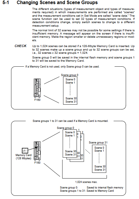
F160-2 allows up to 32 scenes to store different detection conditions. Scenario 0 is stored by default in internal flash memory, while Scenarios 1 to 31 require a Memory Card to be inserted for use. Scene Group packages 32 scenes, with a maximum of 32 scene groups and a total of 1024 scenes. Scene group 0 is still stored in flash memory, while scene groups 1 to 31 are stored on memory cards.
Switching scenes: Press the value on the right side of "Scn" on the basic screen, select the new scene number and confirm, and the system will immediately load the settings for that scene.
Copy Scene: In the scene selection interface, use SHIFT+ESC to bring up the copy/clear/comment menu, select copy and specify the target scene number.
Clear Scene: Similar operations can clear scene data.
Scene annotation: Each scene can be annotated with up to 8 characters for easy recognition.
Engineering Tip: If switching scenes in operating mode, the duration for which the BUSY signal remains ON depends on the duration of the switching operation. If the scene group is switched and the storage card access is slow, it may affect the production cycle. At this time, "Save at switch Scn Group" can be set to OFF in the system settings, but it must be ensured that the changes have been manually saved before switching scenes.
System settings and optimization
Several key settings in System Mode (SYS):
Camera settings: Specify the camera model, and if using smart lighting, also select the lighting model.
Output settings: Select the data output destination (serial/parallel/memory card) and output format (ASCII or binary). The ASCII format allows customization of integer and decimal places, negative sign representation, field separators, and more.
Display settings: You can choose the display image type (static freeze/real-time pass/last NG image/reduced image, etc.), whether to display the overall judgment result, processing time, etc.
Operation customization: Common functions can be assigned to function keys F1~F8, such as "Previous Scene", "Next Scene", "Clear Stored Images", "Capture Display Screen", etc.
Password protection: A 6-8 digit password can be set to prevent unauthorized mode or scene switching.
Startup conditions: It is possible to specify the scene and mode that will automatically enter after startup (it is recommended to set it to MON or RUN), and skip menu selection and camera settings screen to achieve quick startup.
Troubleshooting and Common Problems
8.1 Image Quality Issues
Possible causes and solutions for the phenomenon
The image is too bright or too dark, with insufficient or too strong illumination; Adjust the segmented light intensity of intelligent lighting when the shutter speed is too fast; Reduce the shutter speed; Use BGS to filter grayscale
The image is blurry and the object is moving too fast; If the focus is not accurate, increase the shutter speed; Adjust the camera focal length; Trigger using external synchronization
Noise interference and changes in environmental lighting; Use a light shield for electrical interference; Add filtering (median, smoothing)
8.2 Unstable measurement results
Edge jitter: Increase the noise level and width in edge detection.
Template matching failure: Reduce candidate level or expand search area; If the template itself is deformed, use flexible search or register multiple models.
Position compensation failure: Check if the position compensation area includes feature edges and if the compensation direction is set correctly. If only compensating for X and Y while ignoring the angle, it will cause false detection after the workpiece rotates.
8.3 Communication and output issues
Data not output to PLC: Confirm that the output target of Data in SYS/Output has been selected as "Parallel"; Check if the expression is assigned correctly; Confirm that the input module of the PLC and the output wiring of F160 are consistent.
ERR signal abnormal lighting: In SYS/Measurement control, if "STEP in measure" is set to "ERR ON", when a new trigger signal is received before the measurement is completed, ERR will light up. Can be changed to "OFF" or optimized for bus timing.
Failed to save image: The maximum number of stored images is 35, and when the limit is reached, the new image will overwrite the old image. If long-term storage is required, image data should be backed up to a storage card or computer in TOOL mode.
8.4 Operation error prompt
Draw at least one OR figure ": It is not allowed to use NOT mode without an OR region when drawing the area.
Select midpoint between 2 regions for X and Y ": In position compensation, if a relative angle (midpoint between two regions) is used in the θ direction, then X and Y must also be midpoints and cannot be a single region.
“Cannot measure the angle from this region”: Attempting to output angles from regions that only support center of gravity and area, one should use center of gravity and axis angle or rotation search instead.
Insufficient work memory ": If the registered model is too large or the scene is too complex, the model area can be reduced or unnecessary measurement areas can be deleted.
Maintenance and Data Backup
Flash storage: All changes made in SET mode must be SAVE operated before power off, otherwise data will be lost. SAVE writes scene group 0 and system data to flash memory, and scene groups 1-31 to memory cards.
Backup strategy: It is recommended to use TOOL mode to backup the entire system data or scene group data to the computer through XMODEM/ZMODEM protocol, or directly save it to a storage card. The storage card file can be imported into another F160 for cloning.
Battery inspection: Check the battery status in SYS/System information. If "Replace" appears, the internal lithium battery needs to be replaced (refer to the hard manual steps), otherwise the date, time, and some retention data may be lost.
Regular calibration: If the lens is replaced or the working distance is changed, re calibration is required to maintain physical accuracy.
Summary and on-site quick reference table
Key points of demand operation path
Quickly set new detection SET → adjust image → position compensation → select measurement method → draw area → set judgment conditions and make good use of BGS and filtering
Output measurement values to PLC expression (Data) → SYS/Output Select Parallel Pay attention to matching data format with PLC
Angle positioning rotation search or center of gravity and axis rotation search is slow but adaptable to large angles
Multi variety switching usage scenario (Scene) function can assign buttons for quick switching
Store defective product images SYS/Measurement control settings Only NG. Use SHIFT+up and down keys to view history in operation mode
Hardware Fault Check Error Information Table: When ERR signal lights up, troubleshoot based on the information provided
- ABB
- General Electric
- EMERSON
- Honeywell
- HIMA
- ALSTOM
- Rolls-Royce
- MOTOROLA
- Rockwell
- Siemens
- Woodward
- YOKOGAWA
- FOXBORO
- KOLLMORGEN
- MOOG
- KB
- YAMAHA
- BENDER
- TEKTRONIX
- Westinghouse
- AMAT
- AB
- XYCOM
- Yaskawa
- B&R
- Schneider
- Kongsberg
- NI
- WATLOW
- ProSoft
- SEW
- ADVANCED
- Reliance
- TRICONEX
- METSO
- MAN
- Advantest
- STUDER
- KONGSBERG
- DANAHER MOTION
- Bently
- Galil
- EATON
- MOLEX
- DEIF
- B&W
- ZYGO
- Aerotech
- DANFOSS
- Beijer
- Moxa
- Rexroth
- Johnson
- WAGO
- TOSHIBA
- BMCM
- SMC
- HITACHI
- HIRSCHMANN
- Application field
- XP POWER
- CTI
- TRICON
- STOBER
- Thinklogical
- Horner Automation
- Meggitt
- Fanuc
- Baldor
- SHINKAWA
- Other Brands
- UniOP
- KUKA
- Iba
-
 Laumas TLM8 Ethernet TCP/IP Load Cell Transmitter
 -
 Allen-Bradley 1771-NT2 Thermocouple Input Module
 -
 Siemens 6ES7135-0HF01-0XB0 Analog Output 4AO
 -
 Omron C60H-C6DR-DE-V1 Compact PLC
 -
 HMS Anybus AB7646-F Gateway Profibus to Profinet
 -
 Omron R7M-A10030-BS1 Servo Motor 100W Brake
 -
 Siemens 6SL3555-OPR01-0AA0 G110M Power Supply
 -
 Omron R88M-H10030-B AC Servo Motor 100W
 -
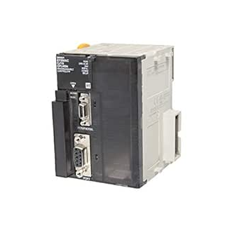
 Omron NJ301-1200 Sysmac NJ3 CPU EtherCAT
 -
 Toshiba H2218592 PLC Control Board Module
 -
 Omron R7A-CEA005S Servo Motor Encoder Cable 5M
 -
 TE.CO TFX 4G 1.5 Grey Cable
 -
 OMRON R88D-HT10 Servo Drive
 -
 OMRON CJ1G-CPU42H PLC CPU
 -
 MASS 106200 Industrial Monitor
 -
 OMRON CJ1W-AD041-V1 Analog Unit
 -
 Phoenix IBS PCI SC/I-T Board
 -
 OMRON ZFX-VS Vision Sensor
 -
 NAIS FP1-C72 PLC Controller
 -
 OMRON R88M-G75030H-BS2 Motor
 -
 SIEMENS A5E02625805-H2 PSU
 -
 Schweitzer SEL-2411 PAC Automation Controller
 -
 Siemens 5WG1-512-1AB11 Switching Actuator KNX
 -
 Stamford MX321-2 Automatic Voltage Regulator AVR
 -
 SCE M68-2000 Dual Axis CNC Servo Drive
 -
 ABB Bailey INNIS21 Network Interface Module
 -
 Omron CJ1W-F159 Loadcell Interface Module
 -
 GE Multilin MMII-PD-1-2-120 Motor Manager II
 -
 Yaskawa CIMR-VZ4A0018FAA VFD 5.5 7.5kW
 -
 Siemens 7SJ6001-5EA00-0DA0 Overcurrent Protection Relay
 -
 GE 531X300CCHAFM5 Drive Control PCB Board
 -
 Siemens 7SJ600 Overcurrent Protection Relay SIPROTEC
 -
 Siemens YSUW8 7683 C98043 A7002 Industrial PC Board
 -
 Omron 3G3MX2 A4055 E High Function Inverter Drive
 -
 Omron NB10W TW01B Interactive Display HMI Panel
 -
 Honeywell 30751044-008 Controller II ROM Board
 -
 Omron CJ1W IDP01 Combination Unit IO PLC
 -
 Omron C500 NC222 Position Control Unit PLC
 -
 Omron Z500 MC15E SW17R Vision System Controller
 -
 Sanyo Denki RS1A10AA RTA AC Servo Motor
 -
 Pilz PSS SB 3006 CN-A Compact Safety System PLC
 -
 OMRON C120-SI022 SYSMAC C120 Unit
 -
 SIEMENS 6SE9212-0DA40 MICROMASTER Inverter
 -
 ABB APBU-44C / APBU-44CE Branching Unit Kit
 -
 FANUC A20B-8100-0663 Mainboard
 -
 ABB 1SDA099907R1 Leakage Protection Relay
 -
 ABB IMMFP12 Multi-Function Module
 -
 OMRON CS1W-DA041 Analog Output Unit
 -
 Yaskawa SGMAS-08ACAHC61 Servo Motor
 -
 Benedetti 30.63/T090 3100MOT013_R1 Servo Motor
 -
 Omron C500-ASC02 ASCII Basic Unit Module
 -
 Yaskawa SGMGV-20DDL6F Servo Motor 1.8kW
 -
 ABB OITF-01C 64437496 D Control Board
 -
 TE.CO TFX 4G 1.5 Industrial Grey Cable
 -
 SCE M68-2000 Servo Drive Dual Axis
 -
 Omron C60H-C6DR-DE-V1 CPU Module PLC
 -
 Siemens 6SL3210-1SE21-8UA0 PM340 Power Module
 -
 Siemens 6GK7443-1EX30-0XE0 CP 443-1 Communications Processor
 -
 Siemens 6SL3210-1KE21-7AP1 SINAMICS G120C Drive
 -
 Phoenix UMK-32 RM/MR-G24/1/PLC Active Module
 -
 Omron NS5 SQ00B V2 HMI Touch Screen Industrial Terminal
 -
 Schneider TSX17 20 Micro PLC AEG Programmable Controller
 -
 Omron Z4M T30V2 Z4M H30V Laser Displacement Sensor System
 -
 Yaskawa SGMPH 04AAA61D OY 400W Servo Motor
 -
 Yaskawa CP 9300MC AC Servo Drive Motion Controller
 -
 Merlin Gerin VIP37PT48 Protection Relay Power Management
 -
 Yaskawa SGDH 05AE Sigma II Servo Driver 0.5kW
 -
 Rieter D90 DSP Autoleveller PLC Drawframe Control
 -
 Saia PCD2 H114 Fast Counting Module Counter
 -
 Axiomatic C902 Motion Board PLC Controller
 -
 Omron C500-TU001 3G2A5-TU001 PLC Teaching Box
 -
 Saia PCD4.M110 PLC CPU Module Programmable Logic Controller
 -
 Yaskawa SGMPH-04AAA61D-OY Sigma-II AC Servo Motor 400W
 -
 Sumitomo Cyclo FAS35-119 Precision Cycloidal Gear Reducer
 -
 Omron IDSC-C1DR-A-E ID Controller PLC Unit
 -
 Omron F350-L100E OVL Image Processing Unit Vision System PLC
 -
 Omron CJ1W-F159 Load Cell Interface Weighing Module
 -
 Bticino MA250 T7314A250 Megatiker PLC Module
 -
 Mitsubishi AJ71QLP21G GI Fiber Optic Network Module
 -
 Omron R88D-HS10 Servo Drive DC Type
 -
 Omron FZ3-L355 Vision Sensor Controller
 -
 Omron C200H-CPU23-E CPU Unit PLC
 -
 Moeller UNIOP MI4-110-KG2 Text Display HMI
 -
 KEB COMBIVERT F5 07.F5.B1B-3B0A Inverter
 -
 Toshiba VFS15-4037PL-W Variable Frequency Drive
 -
 Omron CS1W-SCU31-V1 Serial Communication Unit
 -
 LSIS SV055iG5A-4 AC Drive 5.5kW
 -
Omron CJ1W-F159 Loadcell Interface Unit
-
 Omron CQM1-TC001 Temperature Control Module
 -
 Mitsubishi FX5-SF-MU4T5 Safety Module
 -
 Omron C1000H-CPU01-EV1 CPU Unit
 -
 Yaskawa SGDV-2R8A11A Servo Drive 400V
 -
 Omron 3G3HV-A4055-CUE VFD 5.5kW
 -
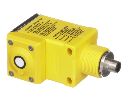
 Omron F160-C15E Vision Sensor Controller
 -
 Schneider ELAU PMC-2 Servo Drive 2.2kW
 -
 Omron CQM1-TC102 Temperature Control Unit
 -
 Omron CS1G-CPU65-EV1 CPU Unit CS1 Series
 -
 Omron CJ1H-CPU66H CPU Unit High Performance
 -
 Saia PCD4.H320 Analog Input Module
 -
 Omron NX-EIC202 EtherNet/IP Coupler Unit
 -
 Omron R88M-H75030 Servo Motor OMNUC Series 750W
 -
 Omron F500-VS Vision Sensor F500 Series Machine Vision
 -
 Omron R88S-H306G Power Unit for Servo Motor OMNUC Series
 -
 Banner Q45ULIU64ACR Ultrasonic Sensor Q45U Series Proximity Mode
 -
 Allen Bradley 1756-IRT8I RTD Thermocouple Input Module ControlLogix
 -
 Siemens Sinumerik 840D SL NCU 720.3B with PLC 317-3 PN DP
 -
 Kollmorgen SERVOSTAR J-06 Servo Drive Danaher Motion
 -
 Omron NX-ECC202 EtherCAT Coupler Unit NX Series
 -
 OMRON CS1W-SCU31-V1 Serial Unit
 -
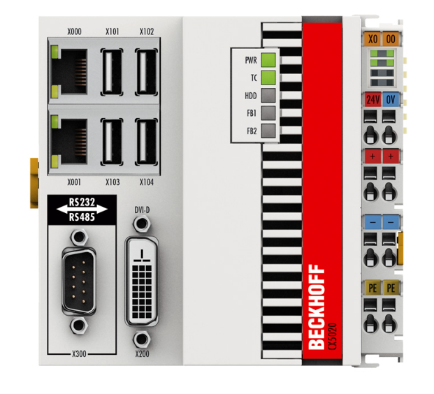 Beckhoff CX5020-0110 Embedded PC PLC
 -
 Omron CJ1M-CPU13-ETN CPU Unit Ethernet
 -
 Omron C60H-C1DR-DE-V1 PLC Controller
 -
Omron CJ1W-PTS51 Thermocouple Input Unit
-
 Omron CJ1W-DA021 Analog Output Module 2 Ch
 -
 Omron CS1W-MAD44 Analog I/O Module
 -
 Omron C500-PRW05-V1 PROM Writer
 -
 Omron CJ1G-CPU45H Loop Control CPU Unit
 -
 ABB PSTX570-600-70 Soft Starter 570A
 -
 PTF Electronic SCR W1Z Power Controller 1150mm
 -
 Omron C500-CT012 High Speed Counter Unit
 -
 NBC Electronics MOD.ES 3 Ton Load Cell
 -
 DeltaOmega XML2 0060 45 4 S A Servo
 -
 REM EC235 Counter Module
 -
 Motor Power SKA DDR 148.30.8.19 Torque Motor
 -
 Delta Tau 4-Axis Interface PLC
 -
 Yokogawa PC10020 AA00 L1Z002 Position Controller
 -
 OMRON C60H-C5DR-DE-V1 PLC
 -
 Burgess PCD4.H320 Motion Control PLC


