
How to install the YAMAHA RCX40 four axis robot controller?
How to install the YAMAHA RCX40 four axis robot controller?
System configuration and hardware parameters
1. Core hardware composition
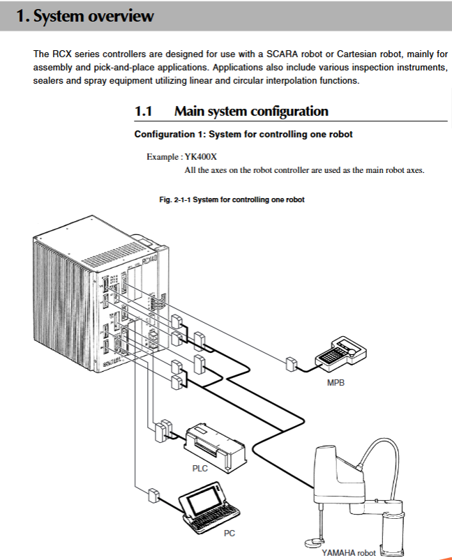
Controller host: Supports up to 4 axis controls, including POWER, SRV, and ERR status indicator lights, compatible with most YAMAHA robot models.
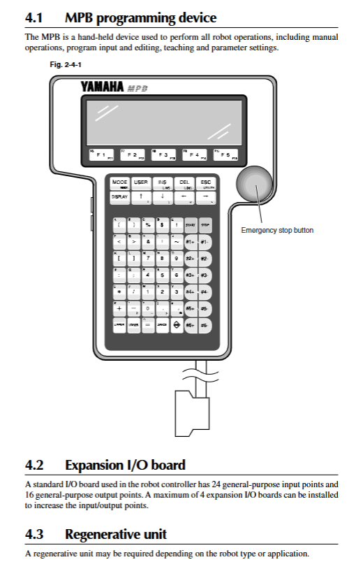
Optional devices: MPB handheld programmer (including emergency stop button), expansion I/O board (up to 4 pieces), regeneration unit (configured as needed).
Cable specification: X-CA 011 system cable (LIYCY-TP 18 × 2 × 0.25 mm ²), available in lengths of 8m/15m/30m, used to connect the host and external devices.
2. Interface configuration details
(1) STD. DIO interface
Input signal: 10 dedicated inputs, 16 universal inputs, supporting NPN/PNP specifications;
Output signal: 11 dedicated outputs and 8 universal outputs. The universal output is the open collector electrode output of Darlington transistor, with a maximum output current of 100mA/channel.
(2) SAFETY I/O interface
Specialized processing of emergency stop inputs, enable switch signals, and other safety related I/O must be connected according to specifications to ensure reliable triggering of emergency stop functions.
(3) Communication and power interface
RS-232C interface: supports data communication with the upper computer, with configurable parameters (baud rate 4800-57600bps, supports XON/XOFF or RTS/CTS stream control);
Power interface: The main power supply is AC200-230V single-phase, with an allowable voltage fluctuation range of -15%~+20%, and the auxiliary power supply is 24VDC;
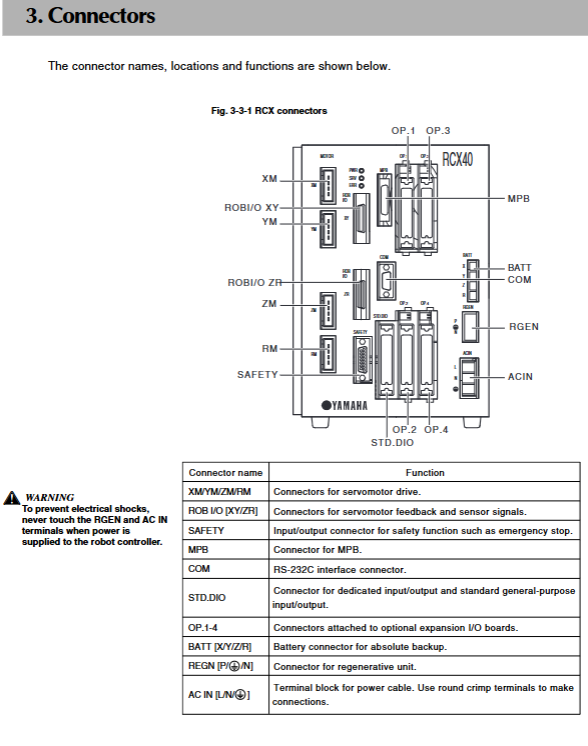
Other interfaces: COM interface (D-SUB 9P female head), BATT battery interface, RGEN regeneration unit interface, etc.
3. Power supply and load specifications
Main power supply: AC200-230V single-phase, requiring external residual current circuit breakers and circuit protectors. It is recommended to use medium slow response circuit protectors (RCX40 recommended rated current 20A);
Load adaptation: resistive load up to 600 Ω, inductive load up to 1mH, capacitive load up to 100 µ F;
Power capacity: Depending on the robot model and number of axes, the power requirement is 600VA-2500VA (e.g. YK400X requires 1000VA, 4-axis Cartesian robot requires a maximum of 2500VA).
Core functions and operating modes
1. Core functional features
(1) Multitasking and Programming Functionality
Multi task parallelism: Up to 8 tasks can be run simultaneously, supporting priority settings. Low priority tasks are paused when high priority tasks are running, supporting I/O parallel processing and interrupt processing to improve overall system efficiency;
Programming Language: Equipped with BASIC like advanced robot language, compatible with industrial robot programming standards SLIM(Standard Language for Industrial Manipulators), Implement fast program execution through compilation, with a maximum of 9999 lines per program and support for storing 100 programs.
(2) Motion control function
Arch motion: can freely set the spatial motion path for picking and placing work, effectively reducing cycle time;
3D CP control: supports 3D interpolation control for linear and circular motion, suitable for complex trajectory requirements;
Manual and automatic motion: Supports PTP (point-to-point), LINEAR (linear), ARCH (arc) motion modes, manual speed can be adjusted step by step or fine tuned, and automatic speed range is 1% -100%.
(3) Data management and communication functions
Data storage: supports editing and storage of point data (0-4000 point numbers), tray definitions, shift coordinates, and hand definitions, and supports data backup to internal Flash ROM or external devices;
Communication function: The RS-232C interface supports online command execution and data transmission, and can be interconnected with most computers with RS-232C ports;
Extended I/O support: Up to 4 expansion I/O boards can be installed, increasing the number of input and output points and adapting to complex industrial scene requirements.
2. Detailed explanation of operating modes
(1) Basic operating mode
Mode Name Core Function Applicable Scenarios
AUTO mode program automatic execution, task switching, speed adjustment (1% -100%), breakpoint setting, point trajectory execution for batch production, program automation running
MANUAL mode robot manual movement, point data teaching/editing, absolute reset, coordinate setting robot debugging, new task point teaching
Program creation/editing/compilation, directory management, user function key registration, program development and modification in GRAM mode
SYSTEM mode parameter configuration (robot/axis/communication parameters), system initialization, initial installation of fault diagnosis controller or system parameter adjustment
Service mode: Maintenance operations within the safety fence, with robot speed limited to below 3% of maximum speed for equipment maintenance and troubleshooting
(2) Other auxiliary modes
UTILITY mode: used for emergency stop cancellation, motor power and servo switch, execution level setting and other maintenance operations;
MONITOR mode: Real time monitoring of I/O status and task status, supporting viewing of signal status such as DI/DO/MO/SI/SO;
DI/DO Monitor mode: Triggered by the PLAY key, it can be overlaid and displayed on the normal operation interface without affecting the operation of the robot.
Installation process and key requirements
1. Preparation before installation
Open box inspection: The equipment is a high-precision device, and before opening the box, it is necessary to check that the packaging box is not severely damaged. After opening the box, check whether the accessories (including MPB programmer, cables, terminal covers, etc.) are complete;
Installation environment: Adequate heat dissipation space should be reserved (top/side ≥ 50mm, rear ≥ 30mm), away from oil, water, vibration sources, and high temperature environments, to avoid blocking the Rear panel fan.
2. Core installation steps
(1) Mechanical installation
Installation method: Supports 4 installation methods, including using rubber feet, front/rear/side installation L-shaped brackets (standard accessories), which need to be installed on a horizontal plane and are not allowed to be placed sideways or upside down;
Handling requirements: Use hand carts and other tools to handle, avoid collision with the front connector of the controller, and prevent damage to the internal PC board.
(2) Electrical connection
Power connection: Connect according to the AC200-230V single-phase specification, with the live wire (L), neutral wire (N), and ground wire connected separately, and the ground wire must be reliably grounded;
Robot cable connection: XM, YM, ROB I/O XY connectors correspond to 1-2 axes, ZM, RM, ROB I/O ZR connectors correspond to 3-4 axes, and must maintain a distance of ≥ 100mm from the power line to avoid confusion of connectors;
Other connections: The MPB programmer needs to be correctly connected to the MPB interface, and if not connected, the MPB terminal needs to be inserted; The absolute battery needs to be connected before the robot cable is connected to avoid origin detection errors.
(3) Wiring specifications
Cable separation: Control lines, communication cables, and robot cables need to be separated from power lines with a spacing of ≥ 100mm, and bundling is prohibited;
Protective measures: The cable should be threaded or fixed to avoid pulling or pulling. When disconnecting the cable, hold the connector instead of the cable itself;
Anti interference: The wiring of electromagnetic contactors, induction motors, and other equipment should be kept away from the controller cables to avoid being laid in the same pipe. If necessary, noise filters and ferrite cores should be installed.
3. Check after installation
Cable connection inspection: Ensure that all connectors are securely plugged in without bent pins or cable damage;
Emergency stop signal check: Confirm that the emergency stop input signal is connected normally and the SAFETY connector is short circuited as required;
Power on test: After power on, observe that the PWR and SRV indicator lights are on and the ERR indicator light is off. If there are no abnormal error reports, the installation is qualified.
Detailed explanation of programming and motion control
1. Core programming operations
(1) Program editing function
Editing mode: Supports switching between Insert and Overwrite modes, allowing for operations such as current insertion, character/line deletion, copy/cut/paste, etc;
Program management: supports program creation, renaming, deletion, and property modification (RW/RO), and can automatically create sample programs (FUTURE programs) for customizing user function keys;
Compilation function: After program editing, the target file needs to be compiled. During the compilation process, syntax errors will be detected, and error messages will be displayed synchronously on the MPB screen.
(2) User Function Key Registration
Define function key functions through the FUTURE program, supporting the allocation of programming mode (P_F series) and manual mode (M-F series) functions;
Example functions include I/O signal control, quick call of motion instructions, etc., supporting up to 15 customizable function keys.
2. Motion control operation
(1) Manual movement and demonstration
Manual movement: Control the movement of each axis through the Jog key, support switching between pulse (joint coordinate) and millimeter (Cartesian coordinate) units, speed can be adjusted step by step through VEL+/- key or 1% precision fine adjustment through VEL++/- key;
Point data teaching: supports direct teaching (manually moving the robot when the servo is turned off) and Jog teaching (moving it with buttons when the servo is turned on), automatically stores teaching data to the specified point number, and supports point annotation editing and copying.
(2) Automatic motion and trajectory control
Program execution: Start the program in AUTO mode, support single step execution (STEP), skip execution (SKIP), breakpoint setting (BREAK), can switch tasks and programs, and adjust motion speed;
Trajectory mode: Supports PTP (point-to-point), ARCH (arc), and LINEAR (linear) interpolation motion. The point trajectory function can verify the actual motion effect of specified point data, and the trajectory speed is 1/10 of the automatic speed.
(3) Coordinate and parameter settings
Standard coordinate setting: SCARA robots need to set standard coordinates and support three methods: 4-point teaching, 3-point teaching, and simple teaching;
Displacement coordinates and hand definition: Supports up to 10 displacement coordinate settings, which can limit the robot's operating area; 4 hand definition settings, suitable for motion compensation in different tool installation scenarios.
Maintenance and fault diagnosis
1. Key points of daily maintenance
(1) Regular maintenance project
Battery maintenance: The absolute battery life is about 1.5 years. B3 battery takes 48 hours to fully charge, B4 battery takes 96 hours, and if the voltage is below 3.5V, it needs to be replaced and recharged;
Verification testing: Conduct verification testing every 10 years, refer to the security manual HI 801 003 E;
Data backup: Regularly backup programs, point data, and parameters to internal Flash ROM or external devices to avoid data loss.
(2) Maintain safety requirements
Before maintenance, cut off all power sources and wait for at least 30 minutes to avoid burns or electric shock caused by high-temperature components and high-voltage circuits;
It is prohibited to disassemble or modify the controller. If parts need to be replaced, please contact YAMAHA or an authorized dealer.
2. Fault diagnosis mechanism
(1) Error messages and historical queries
Supports up to 500 error history storage records, including error codes, occurrence times, and error descriptions, which can be obtained through MPB or RS-232C interfaces;
Common types of errors include abnormal power supply, communication failure, motor overload, absolute reset failure, low battery voltage, etc.
(2) Self diagnostic function
Controller self-test: Perform controller checks in SYSTEM>DIAGNOS mode to detect hardware and system status;
Battery voltage detection: The absolute battery voltage of each axis can be viewed, with a normal range of 3.50-4.3V;
System error details: Display detailed information about serious software errors (error code, occurrence time, related parameters).
(3) Common fault handling
Emergency stop trigger: First, release the emergency stop button, cancel the emergency stop flag in UTILITY mode, and then turn on the motor power;
Incomplete origin: Absolute reset is required, supporting single axis reset and full axis reset. Origin detection methods include marking method, end of travel method, and sensor method;
Communication failure: Check if the RS-232C interface parameters (baud rate, data bits, parity bits) match and if the cable connection is reliable.
Compliance and Disposal Standards
1. Certification and Compliance
Compliant with CE certification related directives (Machinery Directive, Low Voltage Directive, EMC Directive), operating in SAFE mode by default;
Program and Data Storage: We do not guarantee that the internal storage data will remain permanently unchanged and needs to be backed up regularly. YAMAHA is not responsible for any industrial property conflicts caused by the content of the manual.
2. Abandonment and disposal
When disposing of products, they should be treated as industrial waste and are prohibited from being discarded indiscriminately;
The disposal of batteries must comply with local regulations and handle lithium manganese dioxide batteries.
Key question answer
How to ensure the operational safety of RCX40 controller?
The core security mechanism includes graded warning (Warning/CAUTION/NOTE), hardware security design (emergency stop terminals, interlock circuits), wiring and installation protection (line spacing ≥ 100mm, reliable grounding), environmental restrictions (non explosion proof environment, temperature and humidity control);
Operators need to receive professional training and are strictly prohibited from staying within the robot's range of motion. They should regularly check the emergency stop function and safety interlock circuit.
What are the core differences and applicable scenarios of different operating modes?
AUTO mode: Program execution automatically, suitable for mass production;
MANUAL mode: manual movement and demonstration, suitable for debugging and setting up new tasks;
Program mode: Program editing and management, suitable for program development;
SYSTEM mode: parameter configuration and system maintenance, suitable for first-time installation or parameter adjustment;
Service mode: Maintenance within the safety fence, with a speed limit of less than 3%, suitable for equipment maintenance.
How to achieve reliable communication between the controller and external devices?
Connect to the upper computer through the RS-232C interface, configure matching parameters such as baud rate (4800-57600bps), data bits, parity bits, etc., and support XON/XOFF or RTS/CTS stream control;
Realize signal interaction with peripheral devices (sensors, actuators) through STD. DIO interface, correctly wire according to NPN/PNP specifications, ensure reliable signal transmission, and avoid cable interference.
- OMRON
- ABB
- General Electric
- EMERSON
- Honeywell
- HIMA
- ALSTOM
- Rolls-Royce
- MOTOROLA
- Rockwell
- Siemens
- Woodward
- YOKOGAWA
- FOXBORO
- KOLLMORGEN
- MOOG
- KB
- YAMAHA
- BENDER
- TEKTRONIX
- Westinghouse
- AMAT
- AB
- XYCOM
- Yaskawa
- B&R
- Schneider
- KONGSBERG
- NI
- WATLOW
- ProSoft
- SEW
- ADVANCED
- Reliance
- TRICONEX
- METSO
- MAN
- Advantest
- STUDER
- DANAHER MOTION
- Bently
- Galil
- EATON
- MOLEX
- DEIF
- B&W
- ZYGO
- Aerotech
- DANFOSS
- Beijer
- Moxa
- Rexroth
- Johnson
- WAGO
- TOSHIBA
- BMCM
- SMC
- HITACHI
- HIRSCHMANN
- Application field
- XP POWER
- CTI
- TRICON
- STOBER
- Thinklogical
- Horner Automation
- Meggitt
- Fanuc
- Baldor
- SHINKAWA
- Other Brands
- UniOP
- KUKA
- Iba
- Beckhoff
- ADLINK
-
 Basler Electric BE1-700 Digital Protective Relay
 -
 Basler Electric SR8A-2B01B3A Static Voltage Regulator
 -
 Basler Electric SR4A-2B01B3E Static Voltage Regulator
 -
 Basler Electric 9017709102 PC Board
 -
Basler Electric SR4A-2B01B3A Static Voltage Regulator
-
 Basler Electric PRS-250 Veri-Sync Relay
 -
 Basler Electric 9066800102 Excitation Support System
 -
 Basler Electric BE1-87G Generator Differential Relay 9 1708 18 100
 -
 Basler Electric 36T865-2 BE03752001 Power Supply
 -
 Basler Electric M-300 149D940G02 Power Supply
 -
 Basler Electric ACA2040-25GM 4Mp 25Fps Area Scan Camera
 -
 Basler BE1-87G-S1A-A1C-A0N0 Differential Relay
 -
 Basler SR8A-2B06B3E Static Regulator SR8A2B06B3E
 -
 Basler SCP-210 Frequency Controller 9095400100
 -
 Basler BE1-59-A3E-A1J-N1N3F Overvoltage Relay BE159A3EA1JN1N3F
 -
 Basler 9 2011 11 100 Bracket Mounted Terminal Unit
 -
Basler 9 1606 00 101 Voltage Regulator
-
 Basler CBS-377 Current Boost System 9109600102
 -
 Basler 8650C72 Exciter Control Module PCB Rev 5
 -
 Basler C2EE1PA0N1F BE1-32R Reverse Power Relay
 -
 ADLINK HPCI-14S12U - Industrial Control Backplane 12PCI Backplane PCI-14S Passive Backplane
 -
-0010.png) ADLINK PCIe-GIE74C - image acquisition card 4-CH GigE Vision PoE+ Frame Grabber
ADLINK PCIe-GIE74C - image acquisition card 4-CH GigE Vision PoE+ Frame Grabber -
-0010_1.png) ADLINK PCI-8164 - control card 4-Axis Advanced Motion Controller Board
ADLINK PCI-8164 - control card 4-Axis Advanced Motion Controller Board -
 ADLINK PCIe-U304 - 4 Port USB3 PCIe Frame Grabbers USB Screw Hole Card
 -
 ADLINK PCI-9112 - Multi-Function Data Acquisition Card DAQ Card
 -
 ADLINK PCI-7432 - 51-12013-0A50 4-CH Isolated Numérique I/O PCI Cartes Digital I/O Card
 -
 ADLINK PCA-6106P3-0C1 REV.C1 - backplane 6-Slot Passive Backplane Board
 -
 ADLINK PCI-7224 - 24-CH Opto-Isolated Digital I/O PCI Board
 -
 ADLINK CPCI-7433R(G) - Digital Input Board Rear I/O CompactPCI Card
 -
 ADLINK EBP-13E4 - 51-46703-0A30 Industrial PC Backplane Passive Backplane
 -
 ADLINK PCIE-HDV62 - Image acquisition card High Definition Video Frame Grabber
 -
 ADLINK EBP-13E4 - 51-46703-0A30 Industrial Backplane Board Passive Backplane
 -
 ADLINK 90111-B1 / CPCI-6770 - PCB CPU MODULE CompactPCI Single Board Computer
 -
 ADLINK PCI-7248 - DATA ACQUISITION PCI CARD 48-CH Parallel Digital I/O Board
 -
 ADLINK PCI-7230 - 51-12003-0a50 board PCI7230 32-CH Isolated Digital I/O Card
 -
 ADLINK PCI2A000CB - 51-20000-0B30 Multi-Function DAQ Card Baseboard
 -
 ADLINK PCI-8134-005 - 4-Axis Motion Controller Card
 -
 ADLINK PCI-7224 - 24-CH Opto-Isolated Digital I/O PCI Card
 -
 ADLINK PCI-7434 - 64-CH Isolated Digital Output Card
 -
 ADLINK PCI-8132 - motion control card 2-Axis Servo & Stepper Controller
 -
 ADLINK PCI-8134 - Motion Controller PCI Card 4-Axis Controller Board
 -
 ADLINK PCI-8164 - Motion Control Card 51-12406-0A40 4-Axis Controller
 -
 ADLINK 51-12001-0C20 - Circuit Board Data Acquisition Interface Module Hardware
 -
 ADLINK NuPR0-840 - industrial control motherboard Full-Size PICMG CPU Board
 -
 ADLINK PCI-7444 - 51-12023-0A10 card 128-CH Isolated Digital Output Board
 -
 ADLINK PCI-1612B - data acquisition card 4-Port RS-232/422/485 Serial Communication Card
 -
 ADLINK PCI-6208V 009 - 8/16-CH 16-Bit Analog Output Cards PCB-I-E-482=6BX3
 -
 ADLINK NUPRO-935A/LV - industrial control motherboard Full-Size PICMG SBC Board
 -
 ADLINK PCI-9114DG - Multi-Function DAQ Card Data Acquisition PCI Card
 -
 ADLINK ACL-7130 - Data acquisition card Isolated Digital I/O Board
 -
 ADLINK ABX-6300D-4E1-BP - board ABX6300D4E1BP Video Interface Expansion Card
 -
 ADLINK CPCI-6940 - CPCI-6940/D1539/M16-0(EA)-000E 6U CompactPCI Processor Board
 -
 ADLINK NuPRO-760 - industrial control motherboard Half-Size PICMG SBC CPU Board
 -
 ADLINK IMB-M42H (G)-0020 - industrial control motherboard LGA1155 Micro-ATX Mainboard
 -
 ADLINK RTV-24 / PCI-MP4S - 51-12519-1C30 4-Channel Real Time Video Capture Board
 -
 ADLINK PCI-8134 - 4-Axis Servo & Stepper Motion Controller Card
 -
 ADLINK MXC-6101D - V.PC000.002.ST.00 Box PC Configurable Embedded Computer
 -
.png) ADLINK PCI-8134A - 51-12421-0A10 Motion Control Card 4-Axis Controller Card
ADLINK PCI-8134A - 51-12421-0A10 Motion Control Card 4-Axis Controller Card -
 ADLINK DIN-100S / DIN-100SA1 - Technology SCSI-II TB 100-PIN Terminal Block Board
 -
.png) ADLINK DIN-812M001 / DIN812M001 - 51-14034-0A1 51140340A1 Terminal Module Breakout Interface
ADLINK DIN-812M001 / DIN812M001 - 51-14034-0A1 51140340A1 Terminal Module Breakout Interface -
_1.png) ADLINK PCI-8164 - Servo motion control 4-Axis Advanced Controller Card
ADLINK PCI-8164 - Servo motion control 4-Axis Advanced Controller Card -
 ADLINK PCIe-GIE64 - Acquisition card GigE Vision PoE+ Frame Grabber
 -
 ADLINK M-302 - Industrial control motherboard ATX PC Board Mainboard
 -
 ADLINK PCI-8134 - Motion Controller PCI Card 4-Axis Controller Board
 -
 ADLINK PCI-RTV24 - Image capture card Analog Video Frame Grabber
 -
 ADLINK PCI-8102 - Motion control card 2-Axis Servo & Stepper Controller Board
 -
 ADLINK PCI-9112 REV.B1 - Card Multi-Function Data Acquisition Card
 -
 ADLINK HSI-DI32-M-N / HSL-TB32-M-DIN - Discrete I/O MODULE Distributed Automation Module System
 -
 ADLINK PCI-7296 - IO card REV.A3 96-CH Parallel Digital I/O Card
 -
-0020.png) ADLINK DIN-814P-A4 / 814Y - terminal board Motion Control Interface Block
ADLINK DIN-814P-A4 / 814Y - terminal board Motion Control Interface Block -
 ADLINK DIN-814P-A4 - 51-14056-0A10 PCB-I-E-2736=ZA01 Screw Terminal Board Breakout
 -
 ADLINK M-322 - motherboard Industrial Control Computer Mainboard
 -
 ADLINK NUPRO-406 REV:B1 - industrial control motherboard Full-Size PICMG CPU Board
 -
 ADLINK AMP-204C - card DSP-Based 4-Axis Advanced Pulse-Train Controller
 -
 ADLINK HPCI14S REV.B1 - industrial computer baseboard 14-Slot Passive Backplane
 -
 ADLINK PCI-7250 - 8-CH Relay Output & 8-CH Isolated DI PCI Card
 -
 ADLINK EBP-13E2 - baseplate Passive Backplane Industrial Computer Chassis Board
 -
 ADLINK LPCI-3488A - PCI-GPIB card 51-12801-0A30 acquisition card IEEE-488 Interface Board
 -
 ADLINK PCI-6216V-GL - 51-12201-0C30 16-CH 16-Bit Voltage Analog Output Card
 -
 ADLINK ACL-8454 - 16-CH Isolated Digital I/O & 4-CH Counter Card
 -
 ADLINK HPCI-9S7U - backplane Passive Backplane Compatible with NuPRO-A301 852 841 842
 -
 ADLINK DAQ-2010-007 - Simultaneous-Sampling Multi-Function Data Acquisition Card
 -
 ADLINK MP-C154 - 51-64205-0A10 Motion Control Card 4-Axis Controller Board
 -
 ADLINK MXE-202/mSSD16B/WiFi-BT - Matrix Rugged I/O Platform Embedded Fanless Computer
 -
 ADLINK CM-920-R-17 - PC/104-Plus Single Board Computer Module Intel Celeron M
 -
 ADLINK PCI-7250 NSMP - 8-CH Relay Output & 8-CH Isolated DI Card
 -
 ADLINK PCI-8164 - 4-Axis Motion Controller PCI Card W/ Cable and Breakout Box
 -
 ADLINK EMX-100 - Ethernet-based 4-axis Motion Controllers Distributed Motion Module
 -
.png) ADLINK PCI-8134A - Press control card 4-Axis Motion Controller Board
ADLINK PCI-8134A - Press control card 4-Axis Motion Controller Board -
 ADLINK M-845EG REV:3.2 - industrial motherboard Pentium 4 Socket 478 Micro-ATX
 -
 ADLINK PCI-9114A Rev A2 DG - card High-Resolution Multi-Function Data Acquisition Board
 -
 ADLINK IEC-915GV - REV 1.1 Industrial motherboard Socket 478 CPU Board
 -
 ADLINK PCI-9111DG(G) - Data Acquisition Card Multi-Function DAQ Card
 -
 ADLINK HPCI-15S10 REV:B2 - Industrial computer base plate Passive Backplane Board
 -
 ADLINK NuPR0-840 / NuPR0-840DV - industrial control motherboard Full-size PICMG CPU Board
 -
 ADLINK RTV-24 / PCI-MP4S - 51-12519-1C30 4-Channel Real Time Video Capture Board
 -
 ADLINK NUPRO-780 - industrial control motherboard Pentium III Single Board Computer
 -
 ADLINK PCI-7296 - 0050 card 96-CH Opto-Isolated Parallel DIO Card Set
 -
-0040.png) ADLINK NUPRO-780 - industrial control motherboard PICMG Full-Size SBC
ADLINK NUPRO-780 - industrial control motherboard PICMG Full-Size SBC -
 ADLINK PCI-7248 - 51-12006-0A3 002 Pci 7248 48-CH Parallel Digital I/O Card
 -
 ADLINK PCI-7230 - 32-CH Isolated Digital I/O Card
 -
 ADLINK AMP-204C - motion control card 4-Axis Advanced Controller Board
 -
.png) ADLINK PCI-1714UL - Card Ultra High-Speed 4-CH Simultaneous Sampling DAQ
ADLINK PCI-1714UL - Card Ultra High-Speed 4-CH Simultaneous Sampling DAQ -
 ADLINK NuPRO-E330 - industrial computer equipment motherboard PICMG 1.3 SHB SBC
 -
 ADLINK AMP-204C - DSP-Based 4-Axis Advanced Pulse-Train Motion Controller Module
 -
 ADLINK PCI-7256 - 001 51-12206-0A2 REV.A2 LPCI-7256 16-CH Latching Relay Output Card
 -
 ADLINK ND6050 - NUDAM DIGITAL I/0 MODULE Distributed I/O Unit
 -
 ASEM BM100 - Box PC Embedded Fanless Industrial Computer
 -
-3650.png) ADLINK PCI-7250 - PCI Acquisition Card 8-CH Relay Output & Isolated DI Board
ADLINK PCI-7250 - PCI Acquisition Card 8-CH Relay Output & Isolated DI Board -
 ADLINK PCI-8164 - Servo motion control 4-Axis Controller Card
 -
 ADLINK NuPRO-A40H - Industrial Motherboard 51-41807-1A30 OSP LGA1155 H61
 -
 ADLINK ADMAX X300 SERVER - 51066010-0A30 motherboard Multi-Processor Mainboard
 -
 ADLINK CMe-GIE62+ - 51-32903-0A30 control card PC/104-Plus GigE Vision Frame Grabber
 -
 ADLINK NUPRO-780 - industrial control motherboard Full-Size PICMG SBC CPU Board
 -
 ADLINK ETX-AT-N270-18/GKTEL - 51-71111-OB10 motherboard ETX CPU Module Board
 -
 ADLINK DIN-812M - interface module Terminal Block Connection Board
 -
 ADLINK IMB-M42H - industrial control motherboard LGA1155 Micro-ATX Mainboard
 -
ADLINK PXIS-2508 - 8-slot 3U PXI Instrument Chassis Power Hardware Assembly
-
ADLINK AMP-208C - Motion Control card DSP-Based 8-Axis Pulse-Train Controller
-
ADLINK PCI-9111 / PCI-9111DG - Multi-Function Data Acquisition Card DAQ Board
-
ADLINK IEEE-488 GPIB card - Bus Interface Controller Communication Board
-
ADLINK RTV-24 - 51-12519-1C30 image acquisition card Video Frame Grabber Card
-
ADLINK TB-24P/24-01 - Board 24 Way Screw Terminal Breakout Board
-
ADLINK HSL-DI16DO16-DB-NN - 51-23015-0A40 Distributed Discrete I/O Module Set
-
ADLINK PCI-7442 - switch quantity card data acquisition card 64-CH Isolated Card
-
ADLINK ACL-7130 REV. B2 - industrial control capture card Isolated Digital I/O PCI Card
-
ADLINK PCI-6S / PCI6S - Backplane 6-Slot Passive Backplane Chassis Board
-
ADLINK ACL-8113A - card Isolated Digital Input Card


