
HITACHI S10VE Programmable Controller
Pulse counter module: LQC000 (1-phase/2-phase pulse input), supports 1-point pulse counting, with a current consumption of 150mA per module.
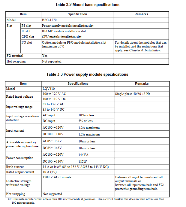
3. Key physical and environmental parameters
Physical specifications: 7-slot mounting base (HSC-1770) with dimensions of 437 × 138.6 × 100mm and weight ≤ 1300g; the thickness of each module is uniformly 34mm (excluding some), and the tightening torque of the mounting screws is 1.0N · m (M4);
Environmental adaptability: operating temperature 0-55 ° C (temperature variation ≤ 10 ° C/hour), storage temperature -20-75 ° C; relative humidity 10-90% RH (no condensation); Seismic resistance: 10-150Hz, 10m/s ² acceleration, 8 minutes/cycle; Impact resistance: 147m/s ² peak acceleration, 11ms half sine wave;
Grounding requirements: Class D grounding (grounding resistance ≤ 100 Ω), separated from the AC panel grounding main line, with a spacing of ≥ 15m.
Installation and commissioning process
1. Key steps and requirements for installation
(1) Preliminary preparation
Confirm installation environment: temperature 0-55 ° C, humidity 10-90% RH, no corrosive gases, dust concentration ≤ 0.1mg/m ³;
Grounding preparation: Construction shall be carried out in accordance with Class D grounding standards, with a grounding resistance of ≤ 100 Ω, and multiple cabinets shall be connected to the ground using a daisy chain connection;
Tool preparation: Use calibrated measuring instruments and compatible screwdrivers (tightening torque 1.0-1.5N · m).
(2) Installation process
Installation base: fixed on the vertical surface of the cabinet, using M5 screws (tightening torque 1.5N · m) to ensure that the insulation lining does not fall off and the metal part of the base does not touch the control cabinet;
Module assembly: Install in the order of "power module → RI/O-IF module → CPU module → option module → PI/O module", align the module with the guide rail, insert it vertically, and tighten the screws;
Battery connection: Before installing the CPU module, insert the main battery cable into the connector according to the corresponding color, and cover the battery cover tightly (hear a snap sound);
Wiring specifications:
Power cable: ≥ 2mm ² shielded twisted pair, with a distance of ≥ 100mm from the network cable;
Remote I/O cable: Select according to the transmission distance (0.75mm ² cable for long distances, ≤ 300m), with single ended grounding of the shielding layer (RI/O-IF side);
Grounding wiring: The FG terminal is connected in a daisy chain and ultimately connected to the power module FG terminal. The cable cross-section is ≥ 2mm ² (inside the cabinet)/≥ 5.5mm ² (outside the cabinet).
(3) Installation gap requirements
The distance between the cabinet and the unit is ≥ 100mm, and the distance between the sides is ≥ 50mm;
There is a requirement for no distance between modules, but one empty slot needs to be left between the high-voltage PI/O module (≥ 100VAC/48VDC) and the CPU/option/simulation module;
Cooling measures: The cabinet needs to have air vents or install fans to ensure that the intake temperature is ≤ 55 ° C.
2. Debugging core processes and tools
(1) Debugging Tools and Environment
Tool: BASE SYSTEM/S10VE (requires administrator privileges to install), supports Windows 7/10 (64 bit), PADT needs to meet 1GHz CPU, 2GB memory, 200MB free hard disk;
Connection: Connect PADT to CPU module ET1/ET2 ports via Ethernet cable, with default IP address 192.192.192.1 (ET1)/192.192.193.1 (ET2).
(2) Debugging key steps
Project creation: Start BASE SYSTEM, create a new project and configure PC numbers and comments, enable C mode requires installation of RPDP;
Network configuration: Set the IP address, subnet mask, and routing information of the CPU's built-in Ethernet or ET.net module, write them, and restart the system;
Program download: Write the program using LADDER DIAGRAM SYSTEM/HI-FLOW SYSTEM, download it to the CPU module, and confirm that there are no syntax errors;
Parameter configuration: Set PI/O installation status, partition (FIX/FREE), I/O point count, remote I/O synchronization mode, etc;
System startup: Turn the CPU RUN/STOP switch to RUN, observe that the RUN LED is constantly on, and confirm that there are no error codes through the indicator;
Function verification: Monitor memory data through MCS function, view module status and error logs through RAS menu, and verify that I/O signal acquisition and execution are normal.
3. Operations and troubleshooting
(1) Key points of daily operation and maintenance
Regular inspection: monthly check the tightness of module screws, LED status, and cable connections; Clean ventilation ducts and verify grounding resistance annually;
Backup strategy: Regularly backup CPU data, including main memory and MRAM data, through the BACKUP STORE SYSTEM, and backup files need to be stored remotely;
Module replacement: It is recommended to replace the power module within 10 years (the lifespan of the aluminum electrolytic capacitor), and replace the main battery within 5 years. When replacing, the power should be turned off;
(2) Common troubleshooting
LED fault indication:
ERR LED constantly on: CPU module has a serious error. Check the error code through the indicator (such as ECF=xxxxx) and refer to the manual for troubleshooting;
- OMRON
- ABB
- General Electric
- EMERSON
- Honeywell
- HIMA
- ALSTOM
- Rolls-Royce
- MOTOROLA
- Rockwell
- Siemens
- Woodward
- YOKOGAWA
- FOXBORO
- KOLLMORGEN
- MOOG
- KB
- YAMAHA
- BENDER
- TEKTRONIX
- Westinghouse
- AMAT
- AB
- XYCOM
- Yaskawa
- B&R
- Schneider
- KONGSBERG
- NI
- WATLOW
- ProSoft
- SEW
- ADVANCED
- Reliance
- TRICONEX
- METSO
- MAN
- Advantest
- STUDER
- DANAHER MOTION
- Bently
- Galil
- EATON
- MOLEX
- DEIF
- B&W
- ZYGO
- Aerotech
- DANFOSS
- Beijer
- Moxa
- Rexroth
- Johnson
- WAGO
- TOSHIBA
- BMCM
- SMC
- HITACHI
- HIRSCHMANN
- Application field
- XP POWER
- CTI
- TRICON
- STOBER
- Thinklogical
- Horner Automation
- Meggitt
- Fanuc
- Baldor
- SHINKAWA
- Other Brands
- UniOP
- KUKA
- Iba
- Beckhoff
-
 Basler DECS-200-2L Digital Excitation Control
 -
 Basler BE1-47N Voltage Phase Sequence Relay
 -
 Basler AEC63-7 Analog Excitation Controller 220-277V
 -
 Basler BE1-50/51B-107 Overcurrent Relay
 -
 Basler Electric BE1‑32R BE1‑E1P‑BON0F Protective Relay
 -
 Basler BE1-25 Solid State Time Overcurrent Relay M1EA6PA5S1F
 -
 Basler MVC 232 Manual Voltage Control Module 90 37000 103 60VAC 55VDC
 -
 Basler RAL6144-16GM Racer GigE Line Scan Camera
 -
 Basler SSR 63-12 Static Voltage Regulator
 -
 Basler BE1-51A Overcurrent Relay
 -
 Basler BE1-87T Solid State Protective Relay
 -
 Basler SR4A2B01B3A Static Voltage Regulator
 -
 Basler SSR 32-12 Static Voltage Regulator
 -
 Basler TRR00696 Transformer 1KVA 115V
 -
 Basler DECS-100-B15 AVR Replacement
 -
Basler BE1-27 Under-Voltage Relay
-
 Basler ACA2000-50GM Interface Module
 -
 Basler AEC63-7 Analog Excitation Controller
 -
 Basler PRS 250 Veri-Sync Relay
 -
 Basler SR4A-2B15B3A Static Voltage Regulator
 -
Basler BE1-32R Power Relay
-
Basler SR8A-2B06B3E Static Voltage Regulator
-
Basler BE1-81 O/U Frequency Relay
-
 Basler BE1-51A-K2E-W6M-B1N0F Overcurrent Relay
 -
Basler BE1-851 Overcurrent Relay G3A1S1 – 48-125V AC/DC
-
 Basler BEI-51 Overcurrent Relay – NSN 5945-01-293-2363
 -
Basler Electric L301KC Protective Relay – L301KC
-
 Basler DECS-100-B15 Automatic Voltage Regulator – Generator AVR
 -
 Basler SR4A-2B15B3A Static Voltage Regulator – SR4A2B15B3A
 -
 Basler UF 312 Under Frequency Protective Module – 9094700100
 -
Basler Electric MVC 232 Manual Control Module – 60VAC 55VDC 20A
-
Basler PRS 250 Veri-Sync Relay – Generator Synchronizing Relay
-
 Basler DECS-100-A05 Digital Regulator Review
 -
 Basler AEM-2020 Analog Expansion Module Specs
 -
 Basler DECS-100-B15 Digital Excitation Specs
 -
Basler Electric 9125600106 Regulator Component
-
Basler BE1-51A-K1E-W6M-B1N0F Overcurrent Relay
-
 Basler MVC-301 MVC 300 Excitation Controller
 -
 Basler SSR 32-12 Static Voltage Regulator
 -
 Basler 9-2849-00-101 Control Module
 -
Basler BE1-51A Overcurrent Relay
-
 Basler BE1-51/27R Overcurrent Relay
 -
 Basler BE1-51 Overcurrent Relay
 -
 Basler SR8A-2B15B3A Static Voltage Regulator
 -
 Basler BE32965001 Transformer and Timer Board
 -
 Basler 9174700100 EL200-7 Excitation Limiter
 -
 Basler BE2000E AVR Voltage Regulator
 -
Basler BE1-87G Differential Relay
-
 Basler BE21834001 Generator Control Module
 -
Basler DECS-100-B15 AVR
-
 Basler D90 96801 100 PCB Card
 -
 Basler XR2002F Voltage Regulator (110 VAC, 48-480 Hz)
 -
 Basler SR8A-2B14B3A Regulator
 -
 Basler 9561500100 Module
 -
 Basler DECS-400 BE1-11 System
 -
 Basler DECS-100-B15 Excitation Control
 -
 Basler SCP 210 Frequency Controller
 -
Basler SR4A-2B15B3A Static Voltage Regulator
-
Basler BE1-32R Power Relay
-
 Basler PIA2400-17GM Power Interface Adapter
 -
 Basler MVC 232 Manual Voltage Control Module
 -
 Basler SSR 32-12 Static Voltage Regulator
 -
Basler 5MW AVR Generator Voltage Regulator
-
 Basler VR63-4B Voltage Regulator
 -
Basler DECS-100-A05 AVR for Engine Generator
-
Basler DECS-100-B15 Automatic Voltage Regulator
-
Basler BE1-32R Directional Power Relay
-
Basler BE1-87B Differential Relay
-
 Basler UFOV 260A Protective Module
 -
 Basler 9-2614-02-100 PCB Rev M
 -
Basler DECS-100-B15 Digital AVR
-
 Basler 9284900103 PS DECS-400N
 -
 Basler D4N3H1U Intertie Protection
 -
 Basler DECS-100-B15 A15 AVR
 -
 Basler KR4F Voltage Regulator
 -
 Basler BE26434 T14 Transformer
 -
 Basler SR8A-2B15B3A Regulator
 -
 Westinghouse 774B472A12 AR Relay
 -
Basler DECS-100-B15 AVR
-
Basler XR2002F Regulator 110V
-
Basler SR125-E Static Regulator
-
Basler SSR 125-12 Regulator
-
Basler MOC2599 Motor Pot
-
 Basler BE1-DFPR Feeder Relay
 -
 Basler CBS 305 Current Boost
 -
Basler BE1-25 AutoSync
-
Basler MVC 300 Voltage Control
-
 Basler BE3-25A AutoSync
 -
 Basler KR7FF Static Regulator
 -
Basler 90-49000-100 Regulator
-
 Basler 880 kVA Dry Type Transformer Specs
 -
Basler Electric BE1-25 Sync-Check Relay Specs
-
 Basler SSR 125-12 Voltage Regulator Specs
 -
 Basler Electric BE1-851 Overcurrent Relay Review
 -
Basler Electric 149D930G02 Control Sub-Assembly
-
 Basler Electric BE1-81O/UT Frequency Relay Specs
 -
 Basler Electric BE1-51/27C Overcurrent Relay
 -
 Basler Electric 149D956G02 Industrial Component
 -
Basler Electric BE1-51A Overcurrent Relay Specs
-
 Basler Electric BE1-40Q Loss of Excitation Relay
 -
Basler DECS-200 Excitation Control System
-
 Basler DECS-200 Voltage Regulator 56-277V AC / 125V DC
 -
Basler BE1-87T Transformer Differential Relay
-
 Basler RDP-110-S1 Protection Relay
 -
 Basler BE1-700V Digital Protective Relay
 -
 Basler BE1-951 Overcurrent Protection System
 -
 Basler DECS-300 Digital Excitation Control
 -
 Basler DECS-200 Digital Excitation Control
 -
 Basler DECS-200-1C Excitation Control System
 -
Basler DECS-200-1L Digital Excitation Control
-
 Basler Electric BE1-GPS Generator Protection System
 -
Basler Electric DECS-200-1C Digital Excitation Controller
-
 Basler Electric DECS125-15 Excitation Control with Power Module
 -
Basler Electric BE1-87G Differential Relay
-
 Basler Electric BE1-11 Protection System I5A3M2P2N0EA00
 -
Basler Electric DECS-200-1C Excitation Control System
-
Basler Electric BE1-11g Generator Protection Relay
-
Basler Electric DECS 125-15-B2C1 V2.0.9 Excitation Control
-
Basler Electric BE1-81O/UT3ED1JA7N2F Frequency Relay
-
Basler Electric BE1-81O/UT3EE1YB7N1F Frequency Relay
-
 Basler Electric DECS-200-1L Digital Excitation Control System
 -
Basler DECS125-15-B2C1 Excitation Control
-
 Basler 9507900205 SSR Retrofit Voltage Regulator
 -
 Basler BE2000E Digital Voltage Regulator
 -
 Basler BE1-GPS Generator Protection System
 -
Basler DECS-250-CN1CN1N Digital Excitation Control
-
 Basler DGC-2020 Genset Controller
 -
Basler BE1-81O UT3ED1LA7N0F Frequency Relay (Variant)


