
HITACHI S10VE Programmable Controller
HITACHI S10VE Programmable Controller
Usage Notes
■ Installation
The programmable controller employs electronic circuit and processor technologies. Note the following in particular:
● When constructing a system, make sure that conditions including the maximum rating, operating power supply voltage range, heat dissipation characteristics, and installation conditions are within the guaranteed operating range described in this manual. Hitachi bears no responsibility for failures or accidents that arise from use of the product outside the guaranteed range.
Even when using the product within the guaranteed range, you must consider the predicted failure rate and failure mode of the product. You can then implement system measures such as making the system failsafe so that operation of the Hitachi product will not cause personal injury, fire, and other consequential damage.
The Programmable Controllers ( ((PCs^{#})) ) in which the CPU unit and PI/O units are installed are neither fireproof, dustproof, nor waterproof. Install the PCs in steel cabinets that are fireproof, dustproof, and waterproof (see Figure 1-1).
#: PCs means the programmable controllers in their entirety including the CPU unit and PI/O units.
● Use the S10VE in an environment that is within the specifications explained in Chapter 3. To ensure long-term stable operation, we recommend that you use the product at room temperature and normal relative humidity (15 to 35°C and 45 to 85% RH). Using the product in a high-temperature or high-humidity environment or an environment where the temperature varies widely over the course of a day leads to a reduced service life.

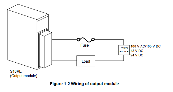
■ Output module
You must provide a short-circuit protection fuse in the load power supply circuit of the output module. Use fuses with the correct load rating. Using the wrong fuse might result in damage to the PCB or housing if the load shortcircuits.
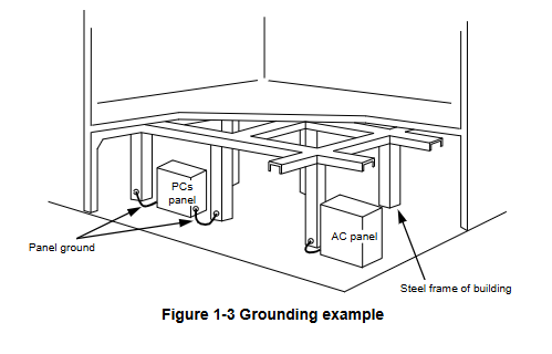
■ Grounding
● Panel grounding specifications
The PCs panel that incorporates the S10VE must be welded to the steel frame of a building that provides at least class D grounding with the ground resistance of 100Ω or less.
Conditions for grounding to the steel frame of a building
- The steel frame is welded together
- The grounding between the earth and the steel frame meets the criteria for class D
If this is not achievable, ground the PCs panel by connecting it to a grounding rod driven into the earth. This provides a low grounding resistance that prevents surrounding noise from entering the PCs.
■ Noise
Do not install the S10VE in or near a panel to which a high-voltage device (such as an inverter) is mounted. If this is unavoidable, use a shielding plate to shield the CPU unit, PI/O units, and cabling from electromagnetic and electrostatic induction.
■ Emergency stop circuit
A partial failure can affect the entire system. Provide an emergency stop circuit as an external circuit. Do not incorporate the emergency stop circuit into programs run on the programmable controller.
■ Disassembling modules
Do not disassemble the modules.
■ Removing/inserting modules
You must turn off the power before removing or inserting a module. To prevent module damage due to static electricity, discharge any static electricity from your body before touching the equipment.
■ Installation of new equipment
When peripheral equipment is added or replaced, check the following aspects of the power supply and grounding:
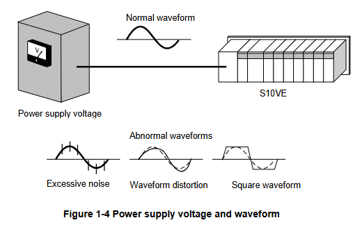
●Power supply
Inspect the power supply voltage and waveform.
- Has the voltage dropped?
- Is there any noise in the power cable?
1. Usage Notes
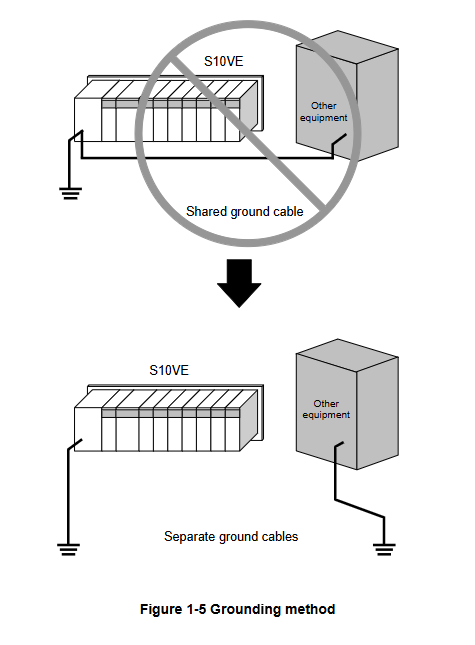
● Grounding
- Make sure that the S10VE does not share its ground cable with other equipment.
- Make sure that no power or lead cables are positioned too closely to a signal cable (such as a remote I/O cable).
2. Overview
2.1 Overview of the system
The S10VE is a programmable controller suited for a wide range of applications from simple condition control to complex arithmetic control. It is capable of simultaneously executing ladder logic, HI-FLOW, and C languages.
2.2 System configuration
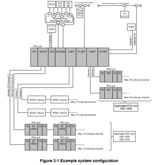
2.2.1 Example system configuration
Figure 2-1 shows an example configuration of an S10VE system.
An S10VE system is made up of a CPU unit, PI/O units, and peripherals.
By installing option modules (OD.RING, D.NET, J.NET, FL.NET, ET.NET) in the CPU unit, an S10VE system can connect to an optical communication network and various other optional networks.
By installing a remote I/O interface module (hereafter RI/O-IF module) in the CPU unit, the system can connect to HSC-1000 and HSC-2100 PI/O units using remote I/O lines. A given system can incorporate both HSC-1000 and HSC-2100 PI/O units.
2.2.2 CPU unit configuration
An S10VE system is made up of a mount base, power supply module, RI/O-IF module, CPU module, and PI/O modules. The mount base incorporates one PS slot (a dedicated slot for the power supply module), one IF slot (a dedicated slot for the RI/O-IF module), one CPU slot (a dedicated slot for the CPU module), and seven I/O slots. The power supply module and CPU module are mandatory components of an S10VE system. Installation of an RI/O-IF module, option modules, and PI/O modules is optional.
- OMRON
- ABB
- General Electric
- EMERSON
- Honeywell
- HIMA
- ALSTOM
- Rolls-Royce
- MOTOROLA
- Rockwell
- Siemens
- Woodward
- YOKOGAWA
- FOXBORO
- KOLLMORGEN
- MOOG
- KB
- YAMAHA
- BENDER
- TEKTRONIX
- Westinghouse
- AMAT
- AB
- XYCOM
- Yaskawa
- B&R
- Schneider
- KONGSBERG
- NI
- WATLOW
- ProSoft
- SEW
- ADVANCED
- Reliance
- TRICONEX
- METSO
- MAN
- Advantest
- STUDER
- DANAHER MOTION
- Bently
- Galil
- EATON
- MOLEX
- DEIF
- B&W
- ZYGO
- Aerotech
- DANFOSS
- Beijer
- Moxa
- Rexroth
- Johnson
- WAGO
- TOSHIBA
- BMCM
- SMC
- HITACHI
- HIRSCHMANN
- Application field
- XP POWER
- CTI
- TRICON
- STOBER
- Thinklogical
- Horner Automation
- Meggitt
- Fanuc
- Baldor
- SHINKAWA
- Other Brands
- UniOP
- KUKA
- Iba
- Beckhoff
-
 Basler DECS-200-2L Digital Excitation Control
 -
 Basler BE1-47N Voltage Phase Sequence Relay
 -
 Basler AEC63-7 Analog Excitation Controller 220-277V
 -
 Basler BE1-50/51B-107 Overcurrent Relay
 -
 Basler Electric BE1‑32R BE1‑E1P‑BON0F Protective Relay
 -
 Basler BE1-25 Solid State Time Overcurrent Relay M1EA6PA5S1F
 -
 Basler MVC 232 Manual Voltage Control Module 90 37000 103 60VAC 55VDC
 -
 Basler RAL6144-16GM Racer GigE Line Scan Camera
 -
 Basler SSR 63-12 Static Voltage Regulator
 -
 Basler BE1-51A Overcurrent Relay
 -
 Basler BE1-87T Solid State Protective Relay
 -
 Basler SR4A2B01B3A Static Voltage Regulator
 -
 Basler SSR 32-12 Static Voltage Regulator
 -
 Basler TRR00696 Transformer 1KVA 115V
 -
 Basler DECS-100-B15 AVR Replacement
 -
Basler BE1-27 Under-Voltage Relay
-
 Basler ACA2000-50GM Interface Module
 -
 Basler AEC63-7 Analog Excitation Controller
 -
 Basler PRS 250 Veri-Sync Relay
 -
 Basler SR4A-2B15B3A Static Voltage Regulator
 -
Basler BE1-32R Power Relay
-
Basler SR8A-2B06B3E Static Voltage Regulator
-
Basler BE1-81 O/U Frequency Relay
-
 Basler BE1-51A-K2E-W6M-B1N0F Overcurrent Relay
 -
Basler BE1-851 Overcurrent Relay G3A1S1 – 48-125V AC/DC
-
 Basler BEI-51 Overcurrent Relay – NSN 5945-01-293-2363
 -
Basler Electric L301KC Protective Relay – L301KC
-
 Basler DECS-100-B15 Automatic Voltage Regulator – Generator AVR
 -
 Basler SR4A-2B15B3A Static Voltage Regulator – SR4A2B15B3A
 -
 Basler UF 312 Under Frequency Protective Module – 9094700100
 -
Basler Electric MVC 232 Manual Control Module – 60VAC 55VDC 20A
-
Basler PRS 250 Veri-Sync Relay – Generator Synchronizing Relay
-
 Basler DECS-100-A05 Digital Regulator Review
 -
 Basler AEM-2020 Analog Expansion Module Specs
 -
 Basler DECS-100-B15 Digital Excitation Specs
 -
Basler Electric 9125600106 Regulator Component
-
Basler BE1-51A-K1E-W6M-B1N0F Overcurrent Relay
-
 Basler MVC-301 MVC 300 Excitation Controller
 -
 Basler SSR 32-12 Static Voltage Regulator
 -
 Basler 9-2849-00-101 Control Module
 -
Basler BE1-51A Overcurrent Relay
-
 Basler BE1-51/27R Overcurrent Relay
 -
 Basler BE1-51 Overcurrent Relay
 -
 Basler SR8A-2B15B3A Static Voltage Regulator
 -
 Basler BE32965001 Transformer and Timer Board
 -
 Basler 9174700100 EL200-7 Excitation Limiter
 -
 Basler BE2000E AVR Voltage Regulator
 -
Basler BE1-87G Differential Relay
-
 Basler BE21834001 Generator Control Module
 -
Basler DECS-100-B15 AVR
-
 Basler D90 96801 100 PCB Card
 -
 Basler XR2002F Voltage Regulator (110 VAC, 48-480 Hz)
 -
 Basler SR8A-2B14B3A Regulator
 -
 Basler 9561500100 Module
 -
 Basler DECS-400 BE1-11 System
 -
 Basler DECS-100-B15 Excitation Control
 -
 Basler SCP 210 Frequency Controller
 -
Basler SR4A-2B15B3A Static Voltage Regulator
-
Basler BE1-32R Power Relay
-
 Basler PIA2400-17GM Power Interface Adapter
 -
 Basler MVC 232 Manual Voltage Control Module
 -
 Basler SSR 32-12 Static Voltage Regulator
 -
Basler 5MW AVR Generator Voltage Regulator
-
 Basler VR63-4B Voltage Regulator
 -
Basler DECS-100-A05 AVR for Engine Generator
-
Basler DECS-100-B15 Automatic Voltage Regulator
-
Basler BE1-32R Directional Power Relay
-
Basler BE1-87B Differential Relay
-
 Basler UFOV 260A Protective Module
 -
 Basler 9-2614-02-100 PCB Rev M
 -
Basler DECS-100-B15 Digital AVR
-
 Basler 9284900103 PS DECS-400N
 -
 Basler D4N3H1U Intertie Protection
 -
 Basler DECS-100-B15 A15 AVR
 -
 Basler KR4F Voltage Regulator
 -
 Basler BE26434 T14 Transformer
 -
 Basler SR8A-2B15B3A Regulator
 -
 Westinghouse 774B472A12 AR Relay
 -
Basler DECS-100-B15 AVR
-
Basler XR2002F Regulator 110V
-
Basler SR125-E Static Regulator
-
Basler SSR 125-12 Regulator
-
Basler MOC2599 Motor Pot
-
 Basler BE1-DFPR Feeder Relay
 -
 Basler CBS 305 Current Boost
 -
Basler BE1-25 AutoSync
-
Basler MVC 300 Voltage Control
-
 Basler BE3-25A AutoSync
 -
 Basler KR7FF Static Regulator
 -
Basler 90-49000-100 Regulator
-
 Basler 880 kVA Dry Type Transformer Specs
 -
Basler Electric BE1-25 Sync-Check Relay Specs
-
 Basler SSR 125-12 Voltage Regulator Specs
 -
 Basler Electric BE1-851 Overcurrent Relay Review
 -
Basler Electric 149D930G02 Control Sub-Assembly
-
 Basler Electric BE1-81O/UT Frequency Relay Specs
 -
 Basler Electric BE1-51/27C Overcurrent Relay
 -
 Basler Electric 149D956G02 Industrial Component
 -
Basler Electric BE1-51A Overcurrent Relay Specs
-
 Basler Electric BE1-40Q Loss of Excitation Relay
 -
Basler DECS-200 Excitation Control System
-
 Basler DECS-200 Voltage Regulator 56-277V AC / 125V DC
 -
Basler BE1-87T Transformer Differential Relay
-
 Basler RDP-110-S1 Protection Relay
 -
 Basler BE1-700V Digital Protective Relay
 -
 Basler BE1-951 Overcurrent Protection System
 -
 Basler DECS-300 Digital Excitation Control
 -
 Basler DECS-200 Digital Excitation Control
 -
 Basler DECS-200-1C Excitation Control System
 -
Basler DECS-200-1L Digital Excitation Control
-
 Basler Electric BE1-GPS Generator Protection System
 -
Basler Electric DECS-200-1C Digital Excitation Controller
-
 Basler Electric DECS125-15 Excitation Control with Power Module
 -
Basler Electric BE1-87G Differential Relay
-
 Basler Electric BE1-11 Protection System I5A3M2P2N0EA00
 -
Basler Electric DECS-200-1C Excitation Control System
-
Basler Electric BE1-11g Generator Protection Relay
-
Basler Electric DECS 125-15-B2C1 V2.0.9 Excitation Control
-
Basler Electric BE1-81O/UT3ED1JA7N2F Frequency Relay
-
Basler Electric BE1-81O/UT3EE1YB7N1F Frequency Relay
-
 Basler Electric DECS-200-1L Digital Excitation Control System
 -
Basler DECS125-15-B2C1 Excitation Control
-
 Basler 9507900205 SSR Retrofit Voltage Regulator
 -
 Basler BE2000E Digital Voltage Regulator
 -
 Basler BE1-GPS Generator Protection System
 -
Basler DECS-250-CN1CN1N Digital Excitation Control
-
 Basler DGC-2020 Genset Controller
 -
Basler BE1-81O UT3ED1LA7N0F Frequency Relay (Variant)


