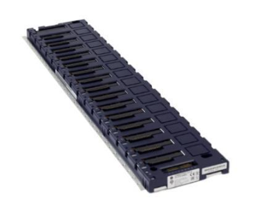
SIEMENS SIMATIC S7-1500/ET 200MP Automation System
Minimum gap: A gap of ≥ 25mm (for heat dissipation and operation space) should be left at the top/bottom of the module. The operating temperature for horizontal installation is 0-60 ℃, and for vertical installation it is 0-40 ℃.
2. Wiring rules
Power wiring:
CPU/Interface Module: Connected to 24V DC (L+, M) through a 4-pole plug, with wire cross-sections of 0.25-2.5mm ² (multiple strands without conduit) and 0.25-1.5mm ² (multiple strands with conduit), and a stripping length of 10-11mm;
System power supply/load power supply: Connected through an encoded power plug, AC input needs to distinguish L1/N, DC input needs to distinguish L+/M, wire stripping length is 7-8mm, torque is 0.5-0.6Nm.
Front connector of I/O module:
Connector type, applicable module width, wiring method, key parameters
Screw terminal 35mm tool fastening supports 2 wires (total cross-section ≤ 1.5mm ²), torque 0.4-0.7Nm
Spring type terminal (push in) 35mm/25mm, tool free hard wire directly inserted, multi strand wire needs to be stripped 8-11mm
The simulation module requires additional installation of shielding brackets and shielding clamps to ensure EMC protection (interference current is grounded through the rail).
Configuration and Debugging Process
1. Software Configuration (STEP 7 TIA Portal)
Basic configuration steps:
Create a project and add S7-1500/ET 200MP devices;
Hardware detection: After connecting to the CPU online, the actual configuration is automatically read through "Hardware detection" to avoid manual input errors;
Address allocation: STEP 7 automatically assigns I/O addresses (digital modules by bit/byte, analog modules by word), supports manual adjustment, can be divided into 32 process image partitions (PIP), PIP 0 is automatically updated, PIP 1-31 can be bound to OB blocks;
Download configuration: The CPU needs to be in STOP mode, and check "Consistent download" to ensure data integrity.
Key configuration functions:
Configuration control: "one main configuration adapts to multiple sub configurations" is realized through control data record (No. 196), which supports module slot adjustment or omission. It is necessary to call WRREC command to transmit data in startup OB;
Block protection: Set know-how protection (password encryption, only displaying interfaces and comments) and copy protection (binding CPU/SIMATIC storage card serial number) for OB/FC/FB/DB.
2. Debugging process
First power on inspection:
Confirm correct wiring (power supply, grounding, I/O circuit);
Insert SIMATIC memory card (required, supports 24MB-2GB, distinguishes program card/firmware update card);
After power on, the CPU performs a self-test (LED flashes all → STOP light turns yellow). If there is a fault, check the diagnostic buffer.
IO testing:
Scan the PROFINET network and test I/O wiring using the PRONETA tool (free of charge);
Monitor/modify variables through STEP 7 "Watch&Force Tables", or directly operate on the CPU display screen (supporting forced peripheral input/output).
Program processing and security protection
1. Fundamentals of Program Processing
Organizational Block (OB): Execute based on event triggers, priority 1-26 (1 lowest, 26 highest), core OB functions are as follows:
OB Number Triggering Event Priority (Default) Function Description
OB 1 loop program 1 main loop executes user program
OB 10-17 timed interrupt 2 triggered at the set time (e.g. every 100ms)
OB 40-47 hardware interrupt 18 triggered by I/O module signal (such as rising edge)
OB 80 time error 22 triggered when cycle time exceeds the limit
OB 121 programming error 7 triggered when there is a syntax error in the program
CPU overload handling: The event queue caches events of the same priority. If the "maximum number of queues" is exceeded, they will be discarded. The time error OB can be triggered through the "event threshold" (such as calling OB 80 when the number of queues is ≥ 1).
2. Safety protection
Access protection: Level 4 permission control, password needs to be configured in CPU properties:
Protection level permission description
Full access to read and write hardware configuration and blocks, no password requirement
Read only access Read only configuration/block, cannot be downloaded, requires password to unlock write permission
HMI access is only available for HMI and diagnostic access, and requires password unlocking for read and write permissions
No access, all access is prohibited. Password unlocking is required
Other protections:
Physical protection: The front cover of the CPU/interface module can be locked (with a diameter of 3mm) or sealed with a seal;
Network protection: Disable unused communication interfaces (such as NTP, PUT/GET), and only allow HTTPS access to the web server.
Maintenance and fault diagnosis
1. Daily maintenance
Module replacement: When replacing the I/O module after power failure, attention should be paid to the coding components (the front connector should be separated from the module when first inserted to ensure that it is only compatible with modules of the same type);
Firmware update: supports 3 methods (online STEP 7, SIMATIC memory card, web server), requires CPU in STOP mode, 2GB card can update CPU 1517/1518 firmware;
- EMERSON
- Honeywell
- CTI
- Rolls-Royce
- General Electric
- Woodward
- Yaskawa
- xYCOM
- Motorola
- Siemens
- Rockwell
- ABB
- B&R
- HIMA
- Construction site
- electricity
- Automobile market
- PLC
- DCS
- Motor drivers
- VSD
- Implications
- cement
- CO2
- CEM
- methane
- Artificial intelligence
- Titanic
- Solar energy
- Hydrogen fuel cell
- Hydrogen and fuel cells
- Hydrogen and oxygen fuel cells
- tyre
- Chemical fiber
- dynamo
- corpuscle
- Pulp and paper
- printing
- fossil
- FANUC
- Food and beverage
- Life science
- Sewage treatment
- Personal care
- electricity
- boats
- infrastructure
- Automobile industry
- metallurgy
- Nuclear power generation
- Geothermal power generation
- Water and wastewater
- Infrastructure construction
- Mine hazard
- steel
- papermaking
- Natural gas industry
- Infrastructure construction
- Power and energy
- Rubber and plastic
- Renewable energy
- pharmacy
- mining
- Plastic industry
- Schneider
- Kongsberg
- NI
- Wind energy
- International petroleum
- International new energy network
- gas
- WATLOW
- ProSoft
- SEW
- wind
- ADVANCED
- Reliance
- YOKOGAWA
- TRICONEX
- FOXBORO
- METSO
- MAN
- Advantest
- ADVANCED
- ALSTOM
- Control Wave
- AB
- AMAT
- STUDER
- KONGSBERG
- MOTOROLA
- DANAHER MOTION
- Bently
- Galil
- EATON
- MOLEX
- Triconex
- DEIF
- B&W
- ZYGO
- Aerotech
- DANFOSS
- KOLLMORGEN
- Beijer
- Endress+Hauser
- MOOG
- KB
- Moxa
- Rexroth
- YAMAHA
- Johnson
- Westinghouse
- WAGO
- TOSHIBA
- TEKTRONIX


Email:wang@kongjiangauto.com

