
Powell PowlVac ® CDR&GCB Series 4 Vacuum Circuit Breaker
Powell PowlVac ® CDR&GCB Series 4 Vacuum Circuit Breaker
Product Core Overview
PowlVac ® Series 4 vacuum circuit breaker is a new generation of metal armored vacuum circuit breaker launched by Powell Industries in the United States, suitable for medium and high voltage power systems ranging from 5kV to 38kV. Its design originated from the first PowlVac circuit breaker in 1982 and has been upgraded and optimized for multiple generations, combining compactness, high reliability, and low maintenance. The product focuses on 'Powered by Safety' ®” The concept provides multiple customized options (such as narrow body design, manual/automatic rack and pinion transmission, intelligent monitoring equipment), which can adapt to the space limitations of existing equipment and meet the protection needs of medium and high voltage circuits in industrial, power and other fields.
Safety regulations and qualification requirements
(1) Definition of Signal Words (in accordance with ANSI Z535.4-2007)
Clarify the risk levels of different safety warnings and guide personnel to identify the degree of danger:
DANGER: Emergency and dangerous situation, failure to avoid may result in death or serious injury.
Warning: Potential dangerous situations that may result in death or serious injury if not avoided.
CAUTION (with safety warning symbol): A dangerous situation that may cause minor/moderate injury.
CAUTION (unsigned): Precautions for operations unrelated to personal injury.
NOTICE: It only involves equipment operation specifications and has no safety risks.
(2) Qualified personnel qualifications (compliant with NFPA 70E) ®)
Operation and maintenance personnel must meet the following conditions:
Having received training on the construction and operation of high-voltage equipment, able to identify and avoid risks.
Master the safety operation procedures such as circuit on/off, grounding, and LOTO (Tag Out).
Familiar with the use of personal protective equipment (PPE) such as insulated gloves, safety helmets, and arc resistant clothing.
Have basic first aid skills.
(3) Key safety rules
Strictly prohibit live operation: all power sources must be disconnected before maintenance to ensure equipment grounding; Do not touch equipment when the control circuit is live.
Energy storage mechanism protection: The equipment adopts an energy storage spring mechanism. When releasing/operating, it is necessary to ensure that personnel and tools are kept away from moving parts to avoid accidental release of the spring causing injury.
Isolation requirement: It is not allowed to use only a disconnected circuit breaker as a means of isolating high-voltage circuits. The circuit breaker must be returned to the "test/disconnect" position or completely withdrawn.
X-ray risk: During high-voltage testing, the vacuum arc extinguishing chamber may generate X-rays. Personnel must maintain a distance of at least 1 meter from the equipment, and the circuit breaker must be fully opened or closed (half open testing is prohibited).
Interlock protection: The equipment is equipped with multiple interlocks (such as rack drive interlock, secondary disconnection interlock), and it is prohibited to modify or bypass the interlock device. In case of abnormalities, the manufacturer should be contacted.
Equipment Description and Core Components
(1) Basic Structure and Function
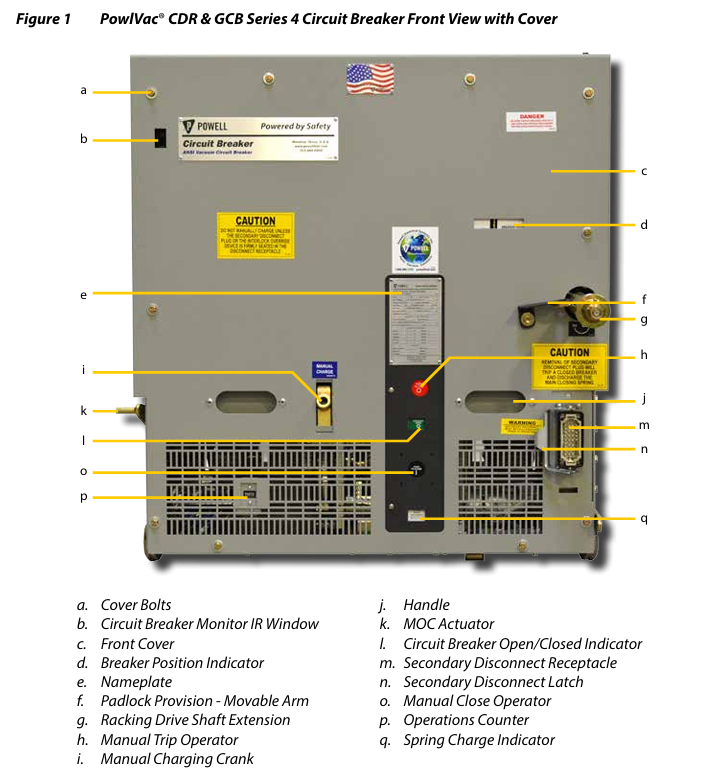
The circuit breaker adopts a sealed vacuum arc extinguishing chamber to control the main circuit. The main circuit is connected to a multi contact primary disconnecting device through parallel copper busbars, and is supported by insulators as a whole; The front of the equipment is an operation panel (including indicator lights and manual operating components), which contains an energy storage mechanism, a rack and pinion transmission mechanism, an interlocking device, and auxiliary switches. It can switch between the "test/disconnect" and "connect" positions and is compatible with metal armored switchgear.
(2) Detailed explanation of core components
Stored Energy Mechanism
Mechanical structure: composed of main closing spring, camshaft, ratchet mechanism, retaining claw, etc., energy is stored by compressing the spring through a charging motor or manual crank, and the energy is released when closing to drive the vacuum arc extinguishing chamber contact to close; Equipped with a disconnect spring, it releases energy during disconnection to achieve rapid disconnection.
Electrical control: including charging motor, motor cut-off switch, anti pump relay (to avoid repeated opening and closing caused by continuous closing signals), closing coil, opening coil (primary/secondary), undervoltage trip device (optional), supporting 24VDC-250VDC/120VAC-240VAC control voltage.
Rack mechanism
Function: Drive the circuit breaker to switch between the "test/disconnect" and "connect" positions inside the switchgear, while controlling the opening and closing of the cabinet panel.
Position indication: The "Circuit Breaker Position Indicator" on the front panel displays the current status (fully displaying "BREAKER CONNECTED" as the connection position and "BREAKER TEST/DISCONNECT" as the test position).
Interlocking protection: Transmission is prohibited in the closed state; The secondary plug can only be unplugged in the "test/disconnect" position; When in the middle position, trigger the "free release" and prohibit closing.
Vacuum Interrupters
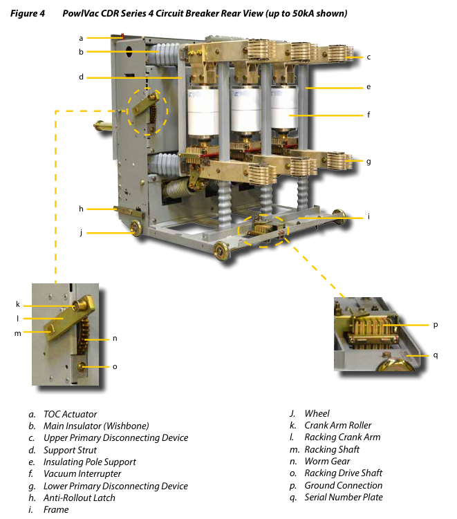
Core function: To achieve arc free breaking of the main circuit through a vacuum environment, different rated currents (25kA-63kA) correspond to different internal structures, and external support needs to be fixed through insulation.
Connection method:
25kA/36kA/50kA models: The arc extinguishing chamber is connected to the primary disconnect device through copper contact blocks, and the sliding contact components achieve multi-path current transmission.
63kA model: connected by copper castings, with built-in multi contact strips to reduce current density.
Switchgear interface components
One time disconnection device: 6 (2 per phase), connected to the fixed end of the cabinet to transmit the main circuit current.
Secondary disconnection device: located in the lower right corner of the equipment, it controls the transmission of power and signals through a plug, and can only be plugged and unplugged in the "test/disconnect" position.
Grounding connection: Spring loaded grounding contact, automatically grounded after insertion into the cabinet, ensuring reliable grounding at all positions.
Anti slip lock: To prevent the circuit breaker from accidentally slipping out of the cabinet, it needs to be manually pressed to unlock before it can be pulled out.
Installation process and operating specifications
(1) Reception and Storage
Receiving inspection: After unpacking, check whether the appearance of the equipment is damaged, and verify that the nameplate information (model, rated value, serial number) is consistent with the order; If there is any damage, immediately file a claim with the transportation company and notify Powell.
Storage requirements:
Indoor storage: temperature between 1 ° C and 60 ° C, humidity ≤ 60% (no condensation), space heater (if equipped) needs to be turned on, or desiccant needs to be placed.
Outdoor storage (outdoor only): Temporary protective covers are required to prevent pollutants from entering, and the temperature should be controlled above freezing point.
(2) Pre installation testing
Before the equipment is put into use, it needs to be tested in the following order to ensure its performance is qualified:
High voltage insulation integrity test:
Use a 2500V insulation resistance meter to measure phase to phase and phase to ground insulation, and record the values (no fixed qualified values, need to track trends).
AC voltage withstand test: According to ANSI C37.20.2 standard, the test voltage for 5kV equipment is 14.25kVAC, and for 15kV equipment it is 27kVAC, with no breakdown for 1 minute; After testing, it is necessary to ground and discharge for at least 1 minute to avoid residual charges causing electric shock.
Vacuum integrity test:
Recommended communication test: Apply 25kVAC in the open state for 10 seconds without breakdown.
DC test (optional): Use full wave rectification of 50kVDC for 5 seconds without breakdown; Prohibit the use of half wave rectification equipment to avoid misjudgment or damage to the arc extinguishing chamber.
Control circuit insulation test: Use a 500V/1000V insulation resistance meter or 1125VAC withstand voltage test for 1 minute. Before testing, disconnect the charging motor (to avoid damage).
Mechanical/Electrical Operation Inspection:
Mechanical operation: Insert the secondary disconnection simulator, manually charge (about 60 crank operations) until the "closing spring has stored energy", and manually open and close to verify that the status indication is normal.
Electrical operation: Verify the automatic energy storage, opening and closing coil action, and anti pumping function of the charging motor through the control circuit of the testing cabinet or switch cabinet.
(3) Cabinet installation and position switching
Insert into the "test/disconnect" position:
Align the cabinet track, push the circuit breaker into contact with the rack and crank and the cabinet slot, and the anti disengagement lock will automatically engage.
Insert the secondary plug and lock it, install the rack drive fixing component (non arc resistant cabinet), and close the cabinet door.
Switch to the 'Connect' position:
Open the "teardrop shaped" cover plate of the cabinet, insert the dedicated rack handle, rotate clockwise for about 22 turns until the position indicator displays "BREAKER CONNECTED"; When the handle torque reaches 35ft lb, the torque limiter is triggered and the rotation stops.
Extraction process:
Ensure that the circuit breaker is open and the spring is discharged. Rotate the handle counterclockwise to the "test/disconnect" position, unplug the secondary plug, press the anti release lock, and pull the circuit breaker out of the cabinet.
Maintenance process and cycle
(1) Maintenance cycle and basic requirements
Routine maintenance: Every 1000-2000 operations or once a year, the cycle needs to be shortened in harsh environments (high dust, high humidity, corrosive gases).
Post fault maintenance: After interrupting the short-circuit current near the rated value, it is necessary to immediately check the arc extinguishing chamber, contacts, and mechanical components.
Preparation before maintenance: Return the equipment to the "test/disconnect" position, disconnect all power sources and ground, and record the reading of the operation counter.
(2) Core maintenance project
Cleaning and Inspection:
Use a vacuum cleaner or dry cloth to remove dust, and prohibit the use of compressed air (to prevent dust from entering the bearings); Insulated components (such as arc extinguishing chamber supports and operating push rods) should be wiped with isopropanol, and the use of detergents is prohibited.
Check if the fasteners are loose, if the contacts are burned, if the energy storage mechanism components are worn, and if damaged parts need to be replaced in a timely manner.
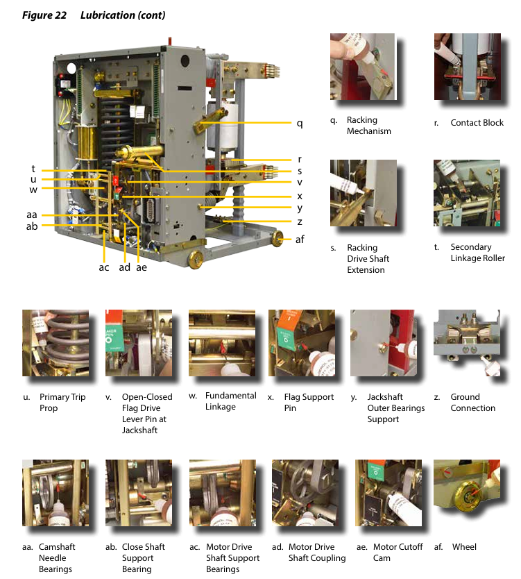
Institutional lubrication (using Powlube-104 kit)
A - Lubricating grease: Apply to moving parts such as camshaft bearings and closing lock shaft surfaces, thin coat and remove excess grease.
B - Lubricating grease: used for one-time disconnection contacts, grounding connection contacts, and other conductive contact surfaces to ensure good contact.
C - Lubricating oil: Drip onto bearings such as ratchet gears, connecting rod shafts, and rack and pinion transmission mechanisms, penetrating into the mating surfaces.
Maintenance of vacuum arc extinguishing chamber
Contact wear inspection: Measure the gap between the operating push rod lock nut and the spring yoke in the closed state. When the gap reaches the "end of life value" marked on the nameplate, the arc extinguishing chamber needs to be replaced.
Vacuum integrity retest: Repeat the vacuum test annually or during maintenance to ensure no leaks.
Institutional adjustment (only after major repairs)
Ratchet holding claw adjustment: By adjusting with eccentric bolts, ensure that the ratchet operates without any "knocking sound" and that manual/electric energy storage is smooth.
Adjustment of the opening system: Adjust the gap between the main opening support rod (0.005 "-0.015") to ensure reliable opening action. Do not trip when tested with a 0.090 "plug gauge, and trip when tested with a 0.030" plug gauge.
Lock check switch adjustment: Insert a 0.045 "plug gauge and adjust the switch position until the contacts are closed, ensuring that the switch is disconnected when opening and closed when resetting.
(3) Optional testing items
**Timing test * *: Closing time ≤ 80ms (coil energized to arc extinguishing chamber contact), opening time<35ms (3 cycles)/<55ms (5 cycles).
Main circuit resistance test: Measure the voltage drop with 100A DC and calculate the resistance value, which should comply with the limit values in the table (such as 15PV36CDR 3000A model ≤ 40 μ Ω).
Spare parts replacement and ordering
(1) Spare parts ordering requirements
Provide complete nameplate information: model, serial number, rated voltage/current/short-circuit current, control voltage.
Clearly describe the spare parts (such as "vacuum arc extinguishing chamber components"), quantity, and if referring to the illustrations in the manual, indicate the location of the components.
(2) Key spare parts and replacement process
Spare part name applicable scenario replacement precautions
The contact wear of the vacuum arc extinguishing chamber component exceeds its service life and the vacuum leakage is 25kA-50kA. The model can be replaced on site (refer to manual 01.4SM.1900); The 63kA model requires professional personnel to operate and Powell needs to be contacted
Sliding contact assembly (≤ 50kA) with contact erosion and exposed copper substrate can be disassembled and reversed for use (only the upper end is worn). After replacement, apply B-grease and bolt torque of 8-12 ft-lb
When the closing/opening coil burns out or fails to operate, the control power supply needs to be disconnected to ensure that the coil voltage is consistent with the prototype number (such as 24VDC/120VAC)
The charging motor does not rotate and energy storage fails. Refer to manual 01.4SM.1200 for reference. After replacement, test the motor direction and energy storage efficiency
Poor grounding of grounding connection components and oxidation of contacts. When disassembling, it is necessary to raise the equipment and apply B-lubricating grease after replacement to ensure reliable grounding
(3) Recommended spare parts list
It is recommended to reserve 1 set of spare parts for every 10 circuit breakers:
Vacuum arc extinguishing chamber (corresponding model), sliding contact assembly, closing/opening coil, charging motor, anti pump relay, locking inspection switch, lubrication kit (Powlube-104).
- OMRON
- ABB
- General Electric
- EMERSON
- Honeywell
- HIMA
- ALSTOM
- Rolls-Royce
- MOTOROLA
- Rockwell
- Siemens
- Woodward
- YOKOGAWA
- FOXBORO
- KOLLMORGEN
- MOOG
- KB
- YAMAHA
- BENDER
- TEKTRONIX
- Westinghouse
- AMAT
- AB
- XYCOM
- Yaskawa
- B&R
- Schneider
- KONGSBERG
- NI
- WATLOW
- ProSoft
- SEW
- ADVANCED
- Reliance
- TRICONEX
- METSO
- MAN
- Advantest
- STUDER
- DANAHER MOTION
- Bently
- Galil
- EATON
- MOLEX
- DEIF
- B&W
- ZYGO
- Aerotech
- DANFOSS
- Beijer
- Moxa
- Rexroth
- Johnson
- WAGO
- TOSHIBA
- BMCM
- SMC
- HITACHI
- HIRSCHMANN
- Application field
- XP POWER
- CTI
- TRICON
- STOBER
- Thinklogical
- Horner Automation
- Meggitt
- Fanuc
- Baldor
- SHINKAWA
- Other Brands
- UniOP
- KUKA
- Iba
- Beckhoff
- ADLINK
-
 Basler Electric BE1-700 Digital Protective Relay
 -
 Basler Electric SR8A-2B01B3A Static Voltage Regulator
 -
 Basler Electric SR4A-2B01B3E Static Voltage Regulator
 -
 Basler Electric 9017709102 PC Board
 -
Basler Electric SR4A-2B01B3A Static Voltage Regulator
-
 Basler Electric PRS-250 Veri-Sync Relay
 -
 Basler Electric 9066800102 Excitation Support System
 -
 Basler Electric BE1-87G Generator Differential Relay 9 1708 18 100
 -
 Basler Electric 36T865-2 BE03752001 Power Supply
 -
 Basler Electric M-300 149D940G02 Power Supply
 -
 Basler Electric ACA2040-25GM 4Mp 25Fps Area Scan Camera
 -
 Basler BE1-87G-S1A-A1C-A0N0 Differential Relay
 -
 Basler SR8A-2B06B3E Static Regulator SR8A2B06B3E
 -
 Basler SCP-210 Frequency Controller 9095400100
 -
 Basler BE1-59-A3E-A1J-N1N3F Overvoltage Relay BE159A3EA1JN1N3F
 -
 Basler 9 2011 11 100 Bracket Mounted Terminal Unit
 -
Basler 9 1606 00 101 Voltage Regulator
-
 Basler CBS-377 Current Boost System 9109600102
 -
 Basler 8650C72 Exciter Control Module PCB Rev 5
 -
 Basler C2EE1PA0N1F BE1-32R Reverse Power Relay
 -
 ADLINK HPCI-14S12U - Industrial Control Backplane 12PCI Backplane PCI-14S Passive Backplane
 -
-0010.png) ADLINK PCIe-GIE74C - image acquisition card 4-CH GigE Vision PoE+ Frame Grabber
ADLINK PCIe-GIE74C - image acquisition card 4-CH GigE Vision PoE+ Frame Grabber -
-0010_1.png) ADLINK PCI-8164 - control card 4-Axis Advanced Motion Controller Board
ADLINK PCI-8164 - control card 4-Axis Advanced Motion Controller Board -
 ADLINK PCIe-U304 - 4 Port USB3 PCIe Frame Grabbers USB Screw Hole Card
 -
 ADLINK PCI-9112 - Multi-Function Data Acquisition Card DAQ Card
 -
 ADLINK PCI-7432 - 51-12013-0A50 4-CH Isolated Numérique I/O PCI Cartes Digital I/O Card
 -
 ADLINK PCA-6106P3-0C1 REV.C1 - backplane 6-Slot Passive Backplane Board
 -
 ADLINK PCI-7224 - 24-CH Opto-Isolated Digital I/O PCI Board
 -
 ADLINK CPCI-7433R(G) - Digital Input Board Rear I/O CompactPCI Card
 -
 ADLINK EBP-13E4 - 51-46703-0A30 Industrial PC Backplane Passive Backplane
 -
 ADLINK PCIE-HDV62 - Image acquisition card High Definition Video Frame Grabber
 -
 ADLINK EBP-13E4 - 51-46703-0A30 Industrial Backplane Board Passive Backplane
 -
 ADLINK 90111-B1 / CPCI-6770 - PCB CPU MODULE CompactPCI Single Board Computer
 -
 ADLINK PCI-7248 - DATA ACQUISITION PCI CARD 48-CH Parallel Digital I/O Board
 -
 ADLINK PCI-7230 - 51-12003-0a50 board PCI7230 32-CH Isolated Digital I/O Card
 -
 ADLINK PCI2A000CB - 51-20000-0B30 Multi-Function DAQ Card Baseboard
 -
 ADLINK PCI-8134-005 - 4-Axis Motion Controller Card
 -
 ADLINK PCI-7224 - 24-CH Opto-Isolated Digital I/O PCI Card
 -
 ADLINK PCI-7434 - 64-CH Isolated Digital Output Card
 -
 ADLINK PCI-8132 - motion control card 2-Axis Servo & Stepper Controller
 -
 ADLINK PCI-8134 - Motion Controller PCI Card 4-Axis Controller Board
 -
 ADLINK PCI-8164 - Motion Control Card 51-12406-0A40 4-Axis Controller
 -
 ADLINK 51-12001-0C20 - Circuit Board Data Acquisition Interface Module Hardware
 -
 ADLINK NuPR0-840 - industrial control motherboard Full-Size PICMG CPU Board
 -
 ADLINK PCI-7444 - 51-12023-0A10 card 128-CH Isolated Digital Output Board
 -
 ADLINK PCI-1612B - data acquisition card 4-Port RS-232/422/485 Serial Communication Card
 -
 ADLINK PCI-6208V 009 - 8/16-CH 16-Bit Analog Output Cards PCB-I-E-482=6BX3
 -
 ADLINK NUPRO-935A/LV - industrial control motherboard Full-Size PICMG SBC Board
 -
 ADLINK PCI-9114DG - Multi-Function DAQ Card Data Acquisition PCI Card
 -
 ADLINK ACL-7130 - Data acquisition card Isolated Digital I/O Board
 -
 ADLINK ABX-6300D-4E1-BP - board ABX6300D4E1BP Video Interface Expansion Card
 -
 ADLINK CPCI-6940 - CPCI-6940/D1539/M16-0(EA)-000E 6U CompactPCI Processor Board
 -
 ADLINK NuPRO-760 - industrial control motherboard Half-Size PICMG SBC CPU Board
 -
 ADLINK IMB-M42H (G)-0020 - industrial control motherboard LGA1155 Micro-ATX Mainboard
 -
 ADLINK RTV-24 / PCI-MP4S - 51-12519-1C30 4-Channel Real Time Video Capture Board
 -
 ADLINK PCI-8134 - 4-Axis Servo & Stepper Motion Controller Card
 -
 ADLINK MXC-6101D - V.PC000.002.ST.00 Box PC Configurable Embedded Computer
 -
.png) ADLINK PCI-8134A - 51-12421-0A10 Motion Control Card 4-Axis Controller Card
ADLINK PCI-8134A - 51-12421-0A10 Motion Control Card 4-Axis Controller Card -
 ADLINK DIN-100S / DIN-100SA1 - Technology SCSI-II TB 100-PIN Terminal Block Board
 -
.png) ADLINK DIN-812M001 / DIN812M001 - 51-14034-0A1 51140340A1 Terminal Module Breakout Interface
ADLINK DIN-812M001 / DIN812M001 - 51-14034-0A1 51140340A1 Terminal Module Breakout Interface -
_1.png) ADLINK PCI-8164 - Servo motion control 4-Axis Advanced Controller Card
ADLINK PCI-8164 - Servo motion control 4-Axis Advanced Controller Card -
 ADLINK PCIe-GIE64 - Acquisition card GigE Vision PoE+ Frame Grabber
 -
 ADLINK M-302 - Industrial control motherboard ATX PC Board Mainboard
 -
 ADLINK PCI-8134 - Motion Controller PCI Card 4-Axis Controller Board
 -
 ADLINK PCI-RTV24 - Image capture card Analog Video Frame Grabber
 -
 ADLINK PCI-8102 - Motion control card 2-Axis Servo & Stepper Controller Board
 -
 ADLINK PCI-9112 REV.B1 - Card Multi-Function Data Acquisition Card
 -
 ADLINK HSI-DI32-M-N / HSL-TB32-M-DIN - Discrete I/O MODULE Distributed Automation Module System
 -
 ADLINK PCI-7296 - IO card REV.A3 96-CH Parallel Digital I/O Card
 -
-0020.png) ADLINK DIN-814P-A4 / 814Y - terminal board Motion Control Interface Block
ADLINK DIN-814P-A4 / 814Y - terminal board Motion Control Interface Block -
 ADLINK DIN-814P-A4 - 51-14056-0A10 PCB-I-E-2736=ZA01 Screw Terminal Board Breakout
 -
 ADLINK M-322 - motherboard Industrial Control Computer Mainboard
 -
 ADLINK NUPRO-406 REV:B1 - industrial control motherboard Full-Size PICMG CPU Board
 -
 ADLINK AMP-204C - card DSP-Based 4-Axis Advanced Pulse-Train Controller
 -
 ADLINK HPCI14S REV.B1 - industrial computer baseboard 14-Slot Passive Backplane
 -
 ADLINK PCI-7250 - 8-CH Relay Output & 8-CH Isolated DI PCI Card
 -
 ADLINK EBP-13E2 - baseplate Passive Backplane Industrial Computer Chassis Board
 -
 ADLINK LPCI-3488A - PCI-GPIB card 51-12801-0A30 acquisition card IEEE-488 Interface Board
 -
 ADLINK PCI-6216V-GL - 51-12201-0C30 16-CH 16-Bit Voltage Analog Output Card
 -
 ADLINK ACL-8454 - 16-CH Isolated Digital I/O & 4-CH Counter Card
 -
 ADLINK HPCI-9S7U - backplane Passive Backplane Compatible with NuPRO-A301 852 841 842
 -
 ADLINK DAQ-2010-007 - Simultaneous-Sampling Multi-Function Data Acquisition Card
 -
 ADLINK MP-C154 - 51-64205-0A10 Motion Control Card 4-Axis Controller Board
 -
 ADLINK MXE-202/mSSD16B/WiFi-BT - Matrix Rugged I/O Platform Embedded Fanless Computer
 -
 ADLINK CM-920-R-17 - PC/104-Plus Single Board Computer Module Intel Celeron M
 -
 ADLINK PCI-7250 NSMP - 8-CH Relay Output & 8-CH Isolated DI Card
 -
 ADLINK PCI-8164 - 4-Axis Motion Controller PCI Card W/ Cable and Breakout Box
 -
 ADLINK EMX-100 - Ethernet-based 4-axis Motion Controllers Distributed Motion Module
 -
.png) ADLINK PCI-8134A - Press control card 4-Axis Motion Controller Board
ADLINK PCI-8134A - Press control card 4-Axis Motion Controller Board -
 ADLINK M-845EG REV:3.2 - industrial motherboard Pentium 4 Socket 478 Micro-ATX
 -
 ADLINK PCI-9114A Rev A2 DG - card High-Resolution Multi-Function Data Acquisition Board
 -
 ADLINK IEC-915GV - REV 1.1 Industrial motherboard Socket 478 CPU Board
 -
 ADLINK PCI-9111DG(G) - Data Acquisition Card Multi-Function DAQ Card
 -
 ADLINK HPCI-15S10 REV:B2 - Industrial computer base plate Passive Backplane Board
 -
 ADLINK NuPR0-840 / NuPR0-840DV - industrial control motherboard Full-size PICMG CPU Board
 -
 ADLINK RTV-24 / PCI-MP4S - 51-12519-1C30 4-Channel Real Time Video Capture Board
 -
 ADLINK NUPRO-780 - industrial control motherboard Pentium III Single Board Computer
 -
 ADLINK PCI-7296 - 0050 card 96-CH Opto-Isolated Parallel DIO Card Set
 -
-0040.png) ADLINK NUPRO-780 - industrial control motherboard PICMG Full-Size SBC
ADLINK NUPRO-780 - industrial control motherboard PICMG Full-Size SBC -
 ADLINK PCI-7248 - 51-12006-0A3 002 Pci 7248 48-CH Parallel Digital I/O Card
 -
 ADLINK PCI-7230 - 32-CH Isolated Digital I/O Card
 -
 ADLINK AMP-204C - motion control card 4-Axis Advanced Controller Board
 -
.png) ADLINK PCI-1714UL - Card Ultra High-Speed 4-CH Simultaneous Sampling DAQ
ADLINK PCI-1714UL - Card Ultra High-Speed 4-CH Simultaneous Sampling DAQ -
 ADLINK NuPRO-E330 - industrial computer equipment motherboard PICMG 1.3 SHB SBC
 -
 ADLINK AMP-204C - DSP-Based 4-Axis Advanced Pulse-Train Motion Controller Module
 -
 ADLINK PCI-7256 - 001 51-12206-0A2 REV.A2 LPCI-7256 16-CH Latching Relay Output Card
 -
 ADLINK ND6050 - NUDAM DIGITAL I/0 MODULE Distributed I/O Unit
 -
 ASEM BM100 - Box PC Embedded Fanless Industrial Computer
 -
-3650.png) ADLINK PCI-7250 - PCI Acquisition Card 8-CH Relay Output & Isolated DI Board
ADLINK PCI-7250 - PCI Acquisition Card 8-CH Relay Output & Isolated DI Board -
 ADLINK PCI-8164 - Servo motion control 4-Axis Controller Card
 -
 ADLINK NuPRO-A40H - Industrial Motherboard 51-41807-1A30 OSP LGA1155 H61
 -
 ADLINK ADMAX X300 SERVER - 51066010-0A30 motherboard Multi-Processor Mainboard
 -
 ADLINK CMe-GIE62+ - 51-32903-0A30 control card PC/104-Plus GigE Vision Frame Grabber
 -
 ADLINK NUPRO-780 - industrial control motherboard Full-Size PICMG SBC CPU Board
 -
 ADLINK ETX-AT-N270-18/GKTEL - 51-71111-OB10 motherboard ETX CPU Module Board
 -
 ADLINK DIN-812M - interface module Terminal Block Connection Board
 -
 ADLINK IMB-M42H - industrial control motherboard LGA1155 Micro-ATX Mainboard
 -
ADLINK PXIS-2508 - 8-slot 3U PXI Instrument Chassis Power Hardware Assembly
-
ADLINK AMP-208C - Motion Control card DSP-Based 8-Axis Pulse-Train Controller
-
ADLINK PCI-9111 / PCI-9111DG - Multi-Function Data Acquisition Card DAQ Board
-
ADLINK IEEE-488 GPIB card - Bus Interface Controller Communication Board
-
ADLINK RTV-24 - 51-12519-1C30 image acquisition card Video Frame Grabber Card
-
ADLINK TB-24P/24-01 - Board 24 Way Screw Terminal Breakout Board
-
ADLINK HSL-DI16DO16-DB-NN - 51-23015-0A40 Distributed Discrete I/O Module Set
-
ADLINK PCI-7442 - switch quantity card data acquisition card 64-CH Isolated Card
-
ADLINK ACL-7130 REV. B2 - industrial control capture card Isolated Digital I/O PCI Card
-
ADLINK PCI-6S / PCI6S - Backplane 6-Slot Passive Backplane Chassis Board
-
ADLINK ACL-8113A - card Isolated Digital Input Card


