
TOSHIBA TOSBERT TM VF-nC1 Industrial Inverter
Applicable motor: only for three-phase induction motors, cannot drive single-phase motors
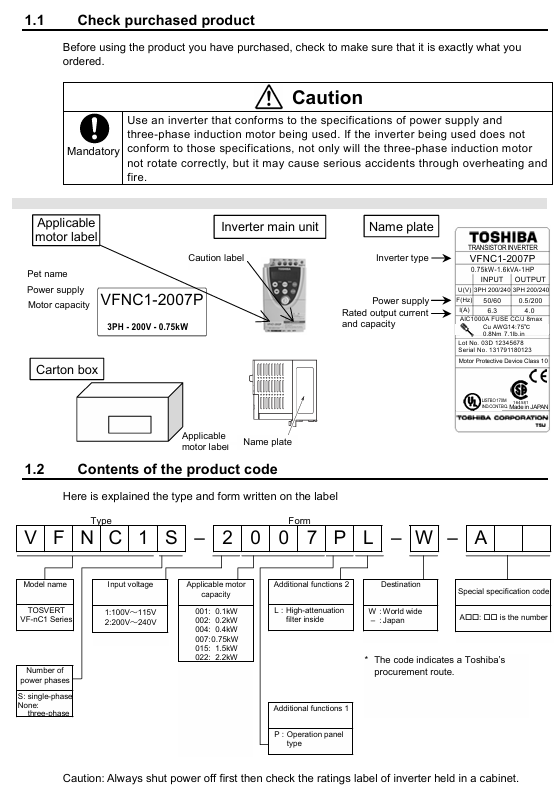
Power and voltage specifications: covering three voltage levels, with specific parameters as shown in the table below:
Voltage level, power range (kW), model example, output current (A), suitable motor capacity (kW)
Single phase 100V level 0.1-0.75 VFNC1S-1001P 0.7-4.0 0.1-0.75
Single phase 200V level 0.2-2.2 VFNC1S-2002P 1.4-10.0 0.2-2.2
Three phase 200V level 0.1-2.2 VFNC1-2001P 0.7-10.0 0.1-2.2
Single phase 200V level (with filter) 0.2-2.2 VFNC1S-2002PL 1.2-10.7 0.2-2.2
Core control method: Adopting sine wave PWM control, the output frequency range is 0.5-200Hz (default 0.5-80Hz), and the voltage/frequency characteristics can be adjusted through parameters (V/f constant, sensorless vector control).
TOSHIBA TOSBERT TM VF-nC1 Industrial Inverter
Product Overview
1.1 Basic Information
Model: TOSBERT TM VF-nC1 Industrial Inverter
Applicable motor: only for three-phase induction motors, cannot drive single-phase motors
Power and voltage specifications: covering three voltage levels, with specific parameters as shown in the table below:
Voltage level, power range (kW), model example, output current (A), suitable motor capacity (kW)
Single phase 100V level 0.1-0.75 VFNC1S-1001P 0.7-4.0 0.1-0.75
Single phase 200V level 0.2-2.2 VFNC1S-2002P 1.4-10.0 0.2-2.2
Three phase 200V level 0.1-2.2 VFNC1-2001P 0.7-10.0 0.1-2.2
Single phase 200V level (with filter) 0.2-2.2 VFNC1S-2002PL 1.2-10.7 0.2-2.2
Core control method: Adopting sine wave PWM control, the output frequency range is 0.5-200Hz (default 0.5-80Hz), and the voltage/frequency characteristics can be adjusted through parameters (V/f constant, sensorless vector control).
Safety regulations
2.1 Warning System
The manual divides safety warnings into two levels, clarifying the consequences of risks and operational requirements:
Typical scenario examples of warning type meanings
Warning: Incorrect operation may result in death or serious injury. Disassembling the front cover while live, connecting input power to output terminals, and operating without grounding
Incorrect handling of the solution may result in minor injuries or property damage. Touching the heat sink, using incompatible chemicals, and installing in a vibrating environment
2.2 Mandatory Safety Requirements
Grounding: D-type grounding (formerly Class 3 grounding) must be used, and the grounding wire diameter should be ≥ 3.5mm ² (refer to the terminal specification table for details) to ensure safe conduction of leakage current in case of fault.
Power off waiting: After disconnecting the input power, wait for at least 15 minutes to confirm that the charge light is off and the DC main circuit voltage is ≤ 45V before touching the terminal.
Installation base: It needs to be fixed on a metal base that can withstand the weight of the equipment to prevent it from falling; Choose NEMA 3R protection model (such as 5000 series) for outdoor/harsh environments.
Emergency stop: It must be equipped with an emergency stop device independent of the frequency converter (such as mechanical braking), and the frequency converter alone cannot achieve immediate shutdown.
Parameter settings
3.1 Parameter Classification and Core Parameters
Parameters are divided into three categories: basic parameters, extended parameters, and special parameters. The core parameters and functions are as follows:
Parameter Category Parameter Code Function Description Adjustment Range Default Values Key Role
Basic parameter CMod instruction mode selection (source of run/stop instructions) 0- Terminal board/1- Panel 1 Determine control mode
FMod frequency setting mode selection: 0- Terminal board/1- Panel, etc. 2. Determine the frequency adjustment method
ACC/DEC acceleration time 1/deceleration time 1 0.1-3000 seconds 10.0s to prevent current overload during startup/shutdown
FH/UL maximum frequency/upper limit frequency 30-200Hz/0.5-FH 80Hz/80Hz limits the maximum operating frequency of the motor
Extended parameter F300 PWM carrier frequency 2/4/8/12/16kHz 12kHz balanced motor noise and inverter losses
F250-252 DC braking parameters (starting frequency/current/time) 0.0-FHHz/0-100/0-20s 0.0Hz/50%/1.0s to achieve rapid shutdown
OLn electronic thermal protection characteristics 0-7 (corresponding to different protections) 0 adaptation standard motor/VF motor protection
Special parameter RUL wizard function (quick setting) 0-5 (5-class wizard) 0 Simplified parameter configuration (such as basic settings)
RUH History Record Function - Display the Last 5 Modified Parameters
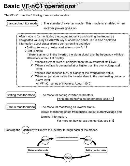
3.2 Parameter Setting Process
Enter setting mode: Press the MON key to switch to "parameter setting mode" (display "RUH");
Parameter selection: Use the △/▽ keys to select the target parameter (such as CMod);
Modify parameters: Press the ENT key to enter editing, and then use the △/▽ keys to adjust the values;
Save parameters: Press the ENT key again, and the parameters and values will alternate to indicate successful saving;
Reset default: Set the basic parameter "Eyp" to 3 to restore all parameters to their factory default values (with the need to shut down first).
Installation and wiring
4.1 Installation environment requirements
Temperature: Operating environment temperature * * -10 ℃ -50 ℃ * *. When the ambient temperature is greater than 40 ℃, the warning label on the top of the equipment should be removed and the rated output current should be reduced (such as the current of the 2007P model dropping from 4A to 3.6A at 40-50 ℃);
Humidity: Relative humidity of 20% -93%, no condensation;
Vibration: Vibration acceleration<5.9m/s ² (10-55Hz), avoid installing near strong vibration equipment such as machine tools;
Other: No dust, corrosive gases, oil mist, keep away from heat sources (such as transformers, heaters).
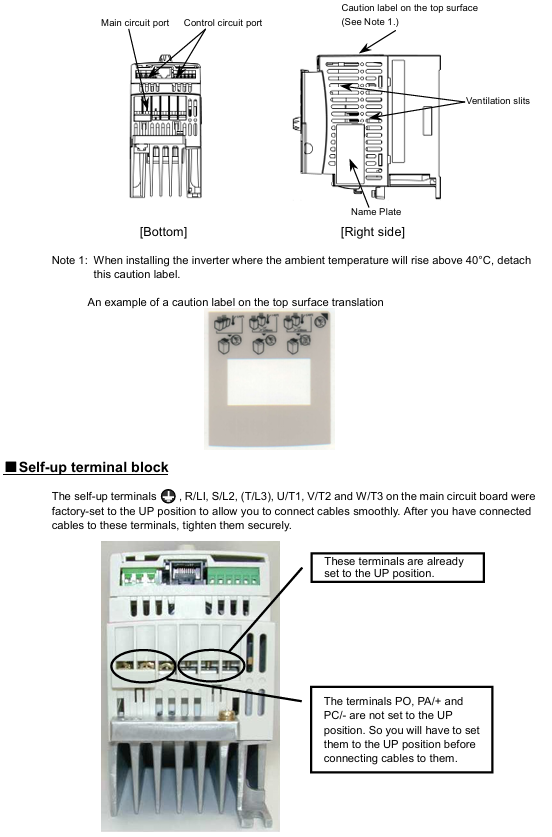
4.2 Terminal Wiring Specification
Main circuit terminals:
Screw specifications: M3 (low power)/M3.5 (high power), tightening torque of 0.8N · m/1.0N · m respectively;
Wiring requirements: Connect the input (R/L1, S/L2, T/L3) to the power supply, and the output (U/T1, V/T2, W/T3) to the motor. Reverse connection is prohibited as it may damage the inverter;
Grounding terminal: It needs to be independently grounded with a wire diameter of ≥ 3.5mm ² (refer to section 10.1 wiring table).
Control circuit terminals:
Screw specifications: M2/M3, wire diameter 0.3-1.5mm ², sheath stripping length 5-6mm;
Wiring taboos: Control circuit and main circuit wiring should be separated (not parallel, not bundled, different conduit) to avoid interference.
4.3 Wiring precautions
It is prohibited to connect capacitive devices (such as noise filters and surge absorbers) on the output side, as this may cause a fire;
The length of the main circuit line is ≤ 30m, and if it exceeds this limit, the wire diameter needs to be increased (for example, for a 200V level 0.75kW motor, a wire length>30m requires a wire of ≥ 2.5mm ²);
When multiple inverters share a power supply, each one needs to be equipped with an independent MCCB (circuit breaker) to avoid the spread of faults.
Operation and monitoring
5.1 Operating Mode
Panel control: Set CMod=1, start with RUN key, stop with STOP key, adjust frequency with △/▽ key;
Terminal control: Set CMod to 0 and control operation by short circuiting the F-CC (forward rotation) and R-CC (reverse rotation) terminals;
Jog operation (JOG): Set the input terminal function to "JOG", the motor runs at a fixed frequency of 5Hz when short circuited, and stops freely after disconnection;
Preset speed operation: By allocating SS1-SS4 terminals (a total of 4 terminals), 15 levels of preset speed can be achieved (F287-F294 parameters need to be set).
5.2 Status Monitoring
Monitoring content: The output frequency, load current (%/A), input voltage (DC), output voltage (%/V), cumulative running time (0.01=1 hour), etc. can be viewed through the "status monitoring mode" (press MON button twice);
Fault display: When tripped, the LED displays a fault code (such as "OC1" indicating acceleration overcurrent), and the FL relay operates (fault output);
Alarm message: Non trip warning (such as "rEr" indicating retry), only prompts not to stop the machine, and attention should be paid to the equipment status.
Fault handling
6.1 Common tripping faults and remedies
Fault code, fault type, possible cause, remedial measures
OC1 acceleration overcurrent acceleration time is too short, motor impedance is too small, extending ACC time (such as changing from 10s to 20s), checking motor insulation
OP2 deceleration overvoltage deceleration time too short, excessive regenerative energy prolongs dEC time, F305 is enabled (overvoltage limited operation)
OH inverter overheating fan fault, poor ventilation, environment overheating. Replace the fan, clean the ventilation opening, and improve environmental heat dissipation
OL2 motor overload, excessive load, long low-speed operation time to reduce load, adjust electronic thermal protection level (OLn=4 compatible with VF motor)
6.2 Fault reset method
Panel reset: In the shutdown state, press the STOP button to display "LLr", then press the STOP button to reset (the fault needs to be eliminated first);
External reset: Short circuit the control terminal RST to CC and disconnect it (RST function needs to be assigned first);
Power off reset: Disconnect the input power supply, wait for 15 minutes, and then power it back on (used in emergency situations, not recommended for frequent operation).
Maintenance and Quality Assurance
7.1 Regular Maintenance Plan
Maintenance Type Cycle Maintenance Content Precautions
Daily inspection of environmental temperature, vibration and noise, load current, and alarm light status without stopping the machine. Visual and instrument checks are required
During the 3-6 month maintenance cycle, terminal tightening, dust removal (ventilation/circuit board), and capacitor inspection must be carried out by cutting off the power for 15 minutes and confirming that the voltage is ≤ 45V before operation
Long term storage: Power on for more than 5 hours every 2 years (motor disconnected), gradually increase the voltage with a transformer to restore capacitor performance, and avoid direct commercial power supply
7.2 Service life and replacement of vulnerable parts
Cooling fan: With a lifespan of approximately 30000 hours (2-3 years of continuous operation), it should be replaced in case of abnormal noise or stoppage;
Electrolytic capacitor: The lifespan of the smoothing capacitor in the main circuit is about 5 years (normal environment). Check for no leakage and ensure that the safety valve is not protruding. Otherwise, replace it;
Fuse: with a lifespan of about 10 years, regularly inspect the appearance, and replace it with the same specification (such as CC/J grade 8A) after melting.
7.3 Warranty Scope
Warranty period: 12 months from the delivery date, only covering the frequency converter host;
Free repair: Parts malfunctions that occur under normal use (such as fans and capacitors);
Disclaimer:
Improper use (such as overload, misconnected power supply);
Self modification/repair;
Natural disasters (fire, earthquake) or abnormal voltage;
Out of range applications (such as driving single-phase motors).
Compliance and Disposal
8.1 Certification Compliance Requirements
CE certification:
EMI filters need to be installed on the input side (such as EMFA2006Z suitable for 200V low power);
Shielded wires are used for the main circuit/control circuit, and the shielding layer is grounded (with a distance of less than 10cm from the inverter);
UL/CSA certification:
Use copper wires above 75 ℃, equipped with CC/J level fuses (such as 4A fuses for the 2002P model);
Branch circuit protection must comply with local electrical regulations (such as NEC in the United States and CEC in Canada).
8.2 Equipment disposal
Mandatory requirement: Waste frequency converters must be disposed of by professional industrial waste disposal institutions (self disassembly is prohibited);
Risk Warning: Self disposal may lead to capacitor explosion and release of toxic gases, violating the Waste Disposal and Cleaning Law;
Contact organization: You can contact Toshiba's regional branches at the end of the manual to obtain compliance disposal channels.
- OMRON
- ABB
- General Electric
- EMERSON
- Honeywell
- HIMA
- ALSTOM
- Rolls-Royce
- MOTOROLA
- Rockwell
- Siemens
- Woodward
- YOKOGAWA
- FOXBORO
- KOLLMORGEN
- MOOG
- KB
- YAMAHA
- BENDER
- TEKTRONIX
- Westinghouse
- AMAT
- AB
- XYCOM
- Yaskawa
- B&R
- Schneider
- KONGSBERG
- NI
- WATLOW
- ProSoft
- SEW
- ADVANCED
- Reliance
- TRICONEX
- METSO
- MAN
- Advantest
- STUDER
- DANAHER MOTION
- Bently
- Galil
- EATON
- MOLEX
- DEIF
- B&W
- ZYGO
- Aerotech
- DANFOSS
- Beijer
- Moxa
- Rexroth
- Johnson
- WAGO
- TOSHIBA
- BMCM
- SMC
- HITACHI
- HIRSCHMANN
- Application field
- XP POWER
- CTI
- TRICON
- STOBER
- Thinklogical
- Horner Automation
- Meggitt
- Fanuc
- Baldor
- SHINKAWA
- Other Brands
- UniOP
- KUKA
- Iba
- Beckhoff
-
 Basler SR32A2B05B3E Static Voltage Regulator
 -
 Basler Electric BE1-59N Ground Fault Overvoltage Relay
 -
 Basler Electric 9110000113 Excitation Module
 -
 Basler Electric 90-72300-114 Control Accessory
 -
 Basler Electric PRS-250 Protection Relay System
 -
Basler Electric BE1-50/51M-109 Overcurrent Relay
-
 Basler Electric SR4A1B10B3E Static Voltage Regulator
 -
 Basler Electric CBS 212 Current Boost System
 -
Basler Electric SR32A2B05B3E Static Voltage Regulator
-
Basler Electric MOC2207 Motor Operated Potentiometer
-
 Basler Electric SR4A1B05A3E Static Voltage Regulator
 -
 Basler Electric BE1-32R Power Relay B2EE1PA0N1F
 -
Basler BEI-81 Underfrequency Relay
-
Basler CBS 212A Current Boost System
-
 Basler SSR 63-12 Static Voltage Regulator
 -
 Basler DGC-2020 Digital Genset Controller
 -
Basler BE1-32 Reverse Power Relay
-
 Basler BE1-50/51B-207 Overcurrent Relay
 -
 Basler BE1-951 Overcurrent Protection System
 -
 Basler 9073800-103 Power Supply
 -
 Basler SCA1300-32FC CCD Camera
 -
Basler 9073800-103 Power Supply
-
Basler SCA1300-32FC CCD Camera
-
 Basler L304KC Protective Relay
 -
 Basler BE3-25-1S1N4 Time Overcurrent Relay
 -
 Basler 9032300113 Excitation Support System
 -
 Basler BE1-59N Ground Overvoltage Relay
 -
 Basler MVC-300 Manual Voltage Control Unit
 -
 Basler MOC2102 Potentiometer
 -
 Basler BE1-87G Generator Differential Relay
 -
 Basler Electric DECS-200 Digital Excitation Control System
 -
Basler Electric DECS 125-15-B2C5 Digital Excitation System
-
 Basler Electric PLA2400-12GM Power Supply
 -
 Basler Electric BE1-50/51B-235 Overcurrent Relay
 -
Basler Electric BE1-27/59 Undervoltage Overvoltage Relay
-
 Basler Electric CEM-2020 Contact Expansion Module
 -
 Basler Electric BE1-32R Solid State Power Relay
 -
 Basler Electric BE1-700 Digital Generator Management Relay
 -
Basler Electric BE1-59N Ground Fault Overvoltage Relay
-
 Basler Electric BE10493002 Protection Module
 -
 Basler Electric BEI-79A1AA5CA3M1F Digital Annunciator
 -
 Basler Electric SSR 32-12 Static Voltage Regulator
 -
Basler Electric BE1-CDS240 Current Differential System
-
Basler Electric BE1-67 Directional Overcurrent Relay
-
 Basler Electric 9121000106 DECS-100 Voltage Controller
 -
Basler Electric BEI-871 Interface Module
-
 Basler Electric 8650C72 Exciter Control Module
 -
 Basler Electric RDP-110-S1 Generator Annunciator
 -
Basler Electric BE1-32O/U Directional Power Relay
-
 Basler Electric BE2000E AVR Voltage Regulator
 -
BASLER ELECTRIC BE1-50F2EA1PA0N0F Instantaneous Overcurrent Relay
-
BASLER ELECTRIC BE1-81T1EE1WA0N1F Underfrequency Relay
-
Basler BE1-67 Directional Overcurrent Relay
-
Basler BE1-25/79TR Reclosing Relay
-
Basler CEM-2020 Contact Expansion Module
-
Basler BE1-11 Overcurrent Protection Relay
-
 Basler BE1-GPS Generator Protective Relay
 -
 BASLER ELECTRIC MVC-300 MANUAL VOLTAGE CONTROL UNIT 9121000106
 -
 Basler Electric KR2FF Voltage Regulator 9 1163 00 109
 -
 BASLER ELECTRIC BE1-87G-G1E-A1K-A0N0F Generator Differential Relay
 -
 Basler BE1-47NE3EA1PA0N2F Phase Sequence Relay
 -
 Basler BE1-81-T1E-E1C-B0N1F Frequency Relay
 -
Basler DECS125-15 Excitation Control
-
Basler BE1-25 Sync-Check Relay
-
 Basler BE1-50/51B Overcurrent Relay
 -
Basler BE1-40Q Loss of Excitation Relay
-
 Basler BE1-50/51M-104 Overcurrent Relay
 -
Basler SSE-N 250-9 KW Shunt Exciter Assembly
-
Basler BE1-87T Transformer Differential Relay
-
 Basler BE1-60 Solid State Protective Relay
 -
Basler DECS125-15 Excitation Control System
-
Basler SR4A-2B15B3A Static Voltage Regulator
-
 Basler BE150BF Overcurrent Relay
 -
 BASLER ELECTRIC BE1A1HF1JD1S2F Overcurrent Relay
 -
Basler BE1-81O Under/Over Frequency Relay
-
 Basler EDM-200 Exciter Diode Monitor
 -
 Basler DECS125-15-B2C5 Excitation Control
 -
 Basler 9261402100 PCB Board
 -
Basler 9252000107 Overcurrent Relay
-
Basler BE1-87T Solid State Protective Relay
-
Basler Electric Phase Directional Overcurrent Relay BE1-Z2JA0N2F
-
 Basler SSR125-12 Static Voltage Regulator
 -
 Basler Electric KR7F VOLTAGE REGULATOR 9116200100
 -
BASLER ELECTRIC BE1-59N-A8E-E1L-N0S1F Ground Overvoltage Relay
-
 Basler SR8A2B06B3A Static Voltage Regulator
 -
BASLER ELECTRIC BE1-81O/UT3EE1KA7N1F Under/Over Frequency Relay
-
 Basler MOC2107 Output Module
 -
 Basler 9125600102 Control Module
 -
 BASLER ELECTRIC BE1-81T1EE1EA2N0F
 -
 Basler BE3-25A Time Overcurrent Relay
 -
Basler Electric CBS 212 Current Boost System 9 2650 00 100 120/240 VAC 50/60Hz
-
Basler Electric BE1-27 Under Voltage Relay A3EC1JA0N5F
-
 Basler BE1-32R Power Relay B2EE1PA0N1F
 -
 Basler DECS100-B15 Automatic Voltage Regulator
 -
 Basler SR8A-2B15B3A Static Voltage Regulator
 -
 Basler AVC63-4 Analog Voltage Regulator
 -
 Basler UFOV 260 A Overvoltage Module
 -
 Basler SR4A-2B16B3A Static Voltage Regulator
 -
Basler SR4A-2B16B3E Static Voltage Regulator
-
Basler SCA1300-32GM CCD Camera
-
 Basler BE34062001 G18 Transformer
 -
Basler BE1-87T Transformer Differential Relay
-
 Basler 9 2849 00 101 DECS Power Module
 -
 Basler RAL6144-16GM Line Scan Camera
 -
 Basler 9269101107 Voltage Regulator Board
 -
Basler BE1-851 Overcurrent Relay
-
Basler SR32A-2B13B3E Static Voltage Regulator
-
 Basler 9 2007 00 100 Current Boost System CBS 305
 -
Basler DECS-100-B11 Automatic Voltage Regulator
-
 Basler BE127 Under Voltage Relay
 -
 Basler 3300C03B1028-G01 Spike Suppressor
 -
Basler SSR 125-12 Static Voltage Regulator
-
Basler SCA1300-32GM CCD Camera Lens Enclosure
-
 Basler BE32965001 Transformer Timer Kit
 -
Basler D90 96801 100 PCB Card
-
 Basler BE1-81-T1E-E1C-A0N1F / 9106400 Underfrequency Relay
 -
 Pro-Face Basler AGP3600-T1-D24 HMI Touch
 -
Basler SR4A2B10B1A Static Voltage Regulator
-
Basler SR8A2B05B3A Static Voltage Regulator
-
Basler BE1-25 Time Overcurrent Relay M1FA6PA4S0F
-
Basler SR4A2B05B3E Static Voltage Regulator
-
 Basler DECS-200-2L Digital Excitation Control
 -
 Basler BE303280001 Control Transformer
 -
Basler 9262103004 Voltage Regulator Board For Basler DECS-400
-
 Basler ICRM-7 Inrush Current Reduction Module
 -
Basler BE1-32R Power Relay
-
BASLER ELECTRIC KR4F VOLTAGE REGULATOR 9042600100 600V 50/60Hz
-
Basler 9222600101 Power Module


