
TOSHIBA TOSBERT VF-S15 series frequency converter
4. Detailed explanation of operation and parameter settings
4.1 Operation panel functions and basic operations
4.1.1 Operation panel layout and button functions
Component Name Function Description
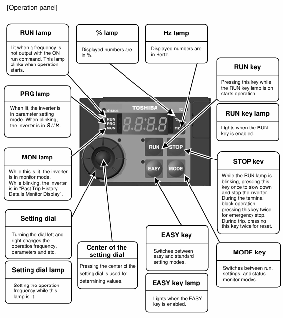
Display screen with 4-digit LED, capable of displaying frequency, parameters, fault codes, monitoring data, etc., supporting numerical and alphabetical display
Run button, press the start motor when the RUN button light is on
STOP key: Press once to slow down and stop during operation; Press the emergency stop button twice during terminal operation; Reset twice in case of malfunction
MODE key mode switch, switch between standard monitoring, parameter settings, and status monitoring modes
EASY key for switching between simple/standard settings mode. When the EASY key light is on, it enters the simple mode (displaying only commonly used parameters)
Set the parameter values and frequency for adjusting the left and right rotation of dialing; Press to confirm settings
When the Hz light is on, the display screen shows the frequency (Hz)
%When the light is on, the display screen shows the percentage (such as load rate)
When the RUN light flashes, it indicates that the motor is running, and when it is constantly on, it indicates that the RUN button is valid
When the PRG light is on, it indicates the parameter setting mode, and when it flashes, it indicates automatic tuning is in progress
When the MON light is on, it indicates the status monitoring mode, and when it flashes, it indicates the monitoring of fault history details
The STATUS light lights up or flashes during CANopen communication
When the Charge light is on, it indicates that there is still high voltage inside the inverter, and it is forbidden to open the terminal cover
4.1.2 Basic operation process
4.1.2.1 Panel operation (default mode, cmod=1)
Power on: The Charge light will turn on and then turn off, and the display screen will show "0.0" (default output frequency).
Frequency setting: Rotate the setting dial and adjust it to the target frequency (such as 50Hz). When fmod=0, there is no need to confirm (power off and save); When fmod=3, press the set dialing confirmation button (flash and save).
Start motor: Press the RUN button, the RUN light flashes, the motor starts according to the set acceleration time, and the display screen shows the real-time output frequency.
Stop motor: Press the STOP button to stop the motor according to the set deceleration time, and the display screen returns to "0.0".
4.1.2.2 Terminal operation (cmod=0)
Parameter settings: Set cmod to 0 (terminal block command mode) and fmod to the corresponding input method (e.g. 1=VIA terminal).
Wiring: Connect the forward (F), reverse (R), and common (CC) terminals (Sink logic) according to the standard connection diagram.
Start: Short circuit F-CC, motor starts; Disconnect F-CC, the motor decelerates and stops.
Emergency stop: Press the STOP button on the panel twice or trigger the external emergency stop device.
4.2 Parameter Setting Core System
4.2.1 Classification of Parameter Modes
Easy setting mode: The EASY key light is on, displaying only 10 commonly used parameters (such as cmod, fmod, acc, dec, ul, ll, etc.), and up to 32 parameters can be custom registered through f751-f782.
Standard setting mode: EASY key light off, displaying all basic and extended parameters (thousands in total), classified by function (such as frequency parameters, protection parameters, communication parameters).
Parameter protection: Parameter protection can be set through f700 (0=allow read/write, 1=prohibit panel writing, 2=prohibit communication writing), or password can be set through f738 (1-9998) to prevent misoperation.
4.2.2 Detailed Explanation of Core Parameters (Classified by Function)
4.2.2.1 Frequency related parameters
Parameter Name Parameter Symbol Adjustment Range Default Value Function Description
The maximum frequency fh is between 30.0-500.0Hz and 80.0Hz, which is the upper limit of the output frequency of the frequency converter and serves as a reference for acceleration/deceleration time
The upper limit frequency ul 0.5-fh (Hz) is the maximum limit of the actual output frequency of the setup menu and cannot exceed fh
The lower limit frequency ll 0.0-ul (Hz) is the lowest limit of the actual output frequency, below which the motor stops
The basic frequency of 1 vl 20.0-500.0Hz is determined by the rated frequency of the setup menu motor (such as 50Hz, 60Hz), which determines the constant torque control area
The basic frequency voltage is 1 vlv 50-330V (240V level), and the output voltage corresponding to the basic frequency of the setup menu needs to match the rated voltage of the motor
Jump frequency 1-3 f270-f272 0.0-fh (Hz) is a frequency point to avoid mechanical resonance, such as f270=50Hz and f271=2Hz (jump width)
Starting frequency f240 0.1-10.0Hz 0.5Hz is the instantaneous output frequency during startup to avoid torque delay. It is recommended to use 0.5-3.0Hz
4.2.2.2 Acceleration/deceleration related parameters
Parameter Name Parameter Symbol Adjustment Range Default Value Function Description
Acceleration time 1 acc 0.0-3600s 10.0s Acceleration time from 0Hz to fh
- OMRON
- ABB
- General Electric
- EMERSON
- Honeywell
- HIMA
- ALSTOM
- Rolls-Royce
- MOTOROLA
- Rockwell
- Siemens
- Woodward
- YOKOGAWA
- FOXBORO
- KOLLMORGEN
- MOOG
- KB
- YAMAHA
- BENDER
- TEKTRONIX
- Westinghouse
- AMAT
- AB
- XYCOM
- Yaskawa
- B&R
- Schneider
- KONGSBERG
- NI
- WATLOW
- ProSoft
- SEW
- ADVANCED
- Reliance
- TRICONEX
- METSO
- MAN
- Advantest
- STUDER
- DANAHER MOTION
- Bently
- Galil
- EATON
- MOLEX
- DEIF
- B&W
- ZYGO
- Aerotech
- DANFOSS
- Beijer
- Moxa
- Rexroth
- Johnson
- WAGO
- TOSHIBA
- BMCM
- SMC
- HITACHI
- HIRSCHMANN
- Application field
- XP POWER
- CTI
- TRICON
- STOBER
- Thinklogical
- Horner Automation
- Meggitt
- Fanuc
- Baldor
- SHINKAWA
- Other Brands
- UniOP
- KUKA
- Iba
- Beckhoff
-
 Basler Electric Phase Directional Overcurrent Relay BE1-Z2JA0N2F
 -
 Basler SSR125-12 Static Voltage Regulator
 -
 Basler Electric KR7F VOLTAGE REGULATOR 9116200100
 -
 BASLER ELECTRIC BE1-59N-A8E-E1L-N0S1F Ground Overvoltage Relay
 -
 Basler SR8A2B06B3A Static Voltage Regulator
 -
 BASLER ELECTRIC BE1-81O/UT3EE1KA7N1F Under/Over Frequency Relay
 -
 Basler MOC2107 Output Module
 -
 Basler 9125600102 Control Module
 -
 BASLER ELECTRIC BE1-81T1EE1EA2N0F
 -
 Basler BE3-25A Time Overcurrent Relay
 -
 Basler Electric CBS 212 Current Boost System 9 2650 00 100 120/240 VAC 50/60Hz
 -
Basler Electric BE1-27 Under Voltage Relay A3EC1JA0N5F
-
 Basler BE1-32R Power Relay B2EE1PA0N1F
 -
 Basler DECS100-B15 Automatic Voltage Regulator
 -
 Basler SR8A-2B15B3A Static Voltage Regulator
 -
 Basler AVC63-4 Analog Voltage Regulator
 -
 Basler UFOV 260 A Overvoltage Module
 -
 Basler SR4A-2B16B3A Static Voltage Regulator
 -
Basler SR4A-2B16B3E Static Voltage Regulator
-
 Basler SCA1300-32GM CCD Camera
 -
 Basler BE34062001 G18 Transformer
 -
Basler BE1-87T Transformer Differential Relay
-
 Basler 9 2849 00 101 DECS Power Module
 -
 Basler RAL6144-16GM Line Scan Camera
 -
 Basler 9269101107 Voltage Regulator Board
 -
 Basler BE1-851 Overcurrent Relay
 -
 Basler SR32A-2B13B3E Static Voltage Regulator
 -
 Basler 9 2007 00 100 Current Boost System CBS 305
 -
 Basler DECS-100-B11 Automatic Voltage Regulator
 -
 Basler BE127 Under Voltage Relay
 -
 Basler 3300C03B1028-G01 Spike Suppressor
 -
 Basler SSR 125-12 Static Voltage Regulator
 -
Basler SCA1300-32GM CCD Camera Lens Enclosure
-
 Basler BE32965001 Transformer Timer Kit
 -
 Basler D90 96801 100 PCB Card
 -
 Basler BE1-81-T1E-E1C-A0N1F / 9106400 Underfrequency Relay
 -
 Pro-Face Basler AGP3600-T1-D24 HMI Touch
 -
Basler SR4A2B10B1A Static Voltage Regulator
-
Basler SR8A2B05B3A Static Voltage Regulator
-
Basler BE1-25 Time Overcurrent Relay M1FA6PA4S0F
-
Basler SR4A2B05B3E Static Voltage Regulator
-
 Basler DECS-200-2L Digital Excitation Control
 -
 Basler BE303280001 Control Transformer
 -
Basler 9262103004 Voltage Regulator Board For Basler DECS-400
-
 Basler ICRM-7 Inrush Current Reduction Module
 -
Basler BE1-32R Power Relay
-
 BASLER ELECTRIC KR4F VOLTAGE REGULATOR 9042600100 600V 50/60Hz
 -
Basler 9222600101 Power Module
-
 Basler SR8A-2B15B3A Static Voltage Regulator
 -
BASLER BE1-87G G1E A1L A0N1P Generator Differential Relay w/ Reactor 9170818100
-
Basler 9284900101 DECS Power Module
-
 Basler PRS250 Veri-Sync Relay
 -
 Basler BE 12296 001 Transformer
 -
Basler 905970-104 Rev.M Voltage Regulator
-
Basler BE1-87T Transformer Differential Relay
-
 Basler SR8A-2B15B3A Static Voltage Regulator
 -
Basler SR32A2B05B3E Static Voltage Regulator
-
 Basler SR4A-2B16B3A Static Voltage Regulator
 -
 Basler SR32A-2B13B3E Static Voltage Regulator
 -
 Basler KR4F Voltage Regulator 9042600100
 -
 Basler SSR 32-12 Static Voltage Regulator 400Hz
 -
 Basler CBS 212A Current Boost System
 -
 Basler MVC236 Manual Control Module
 -
Basler UFOV Protective Module 9040000100
-
 Basler SSR 125-12 Static Voltage Regulator
 -
Basler SR4A2B10A3E Static Voltage Regulator
-
Basler BE1-25 Solid State Time Overcurrent Relay
-
 Basler MVC 232 Manual Voltage Control Module
 -
Basler PRS 250 Veri-Sync Relay
-
Basler UFOV 260A Under Frequency Over Voltage Relay
-
Basler RUL2098-10GC Load Relay
-
 Basler 9 1049 04 100 PC Board
 -
Basler 125-12 Static Voltage Regulator
-
Basler PRS 250 Veri-Sync Relay
-
Basler 9185900102 SSR 125-12 Regulator
-
Basler BE12819001 Reactor
-
 Teradyne 535-100-00 Power Supply
 -
 Basler BE1-67 Directional OC Relay
 -
 Basler PRP110 Reverse Power Relay
 -
 Basler BE30631001 Isolation Transformer
 -
 Basler DECS-200-2L Digital Excitation Control
 -
 Basler BE1-47N Voltage Phase Sequence Relay
 -
 Basler AEC63-7 Analog Excitation Controller 220-277V
 -
Basler BE1-50/51B-107 Overcurrent Relay
-
 Basler Electric BE1‑32R BE1‑E1P‑BON0F Protective Relay
 -
Basler BE1-25 Solid State Time Overcurrent Relay M1EA6PA5S1F
-
 Basler MVC 232 Manual Voltage Control Module 90 37000 103 60VAC 55VDC
 -
Basler RAL6144-16GM Racer GigE Line Scan Camera
-
Basler SSR 63-12 Static Voltage Regulator
-
 Basler BE1-51A Overcurrent Relay
 -
Basler BE1-87T Solid State Protective Relay
-
Basler SR4A2B01B3A Static Voltage Regulator
-
 Basler SSR 32-12 Static Voltage Regulator
 -
 Basler TRR00696 Transformer 1KVA 115V
 -
 Basler DECS-100-B15 AVR Replacement
 -
Basler BE1-27 Under-Voltage Relay
-
 Basler ACA2000-50GM Interface Module
 -
 Basler AEC63-7 Analog Excitation Controller
 -
Basler PRS 250 Veri-Sync Relay
-
 Basler SR4A-2B15B3A Static Voltage Regulator
 -
Basler BE1-32R Power Relay
-
Basler SR8A-2B06B3E Static Voltage Regulator
-
Basler BE1-81 O/U Frequency Relay
-
 Basler BE1-51A-K2E-W6M-B1N0F Overcurrent Relay
 -
Basler BE1-851 Overcurrent Relay G3A1S1 – 48-125V AC/DC
-
 Basler BEI-51 Overcurrent Relay – NSN 5945-01-293-2363
 -
Basler Electric L301KC Protective Relay – L301KC
-
 Basler DECS-100-B15 Automatic Voltage Regulator – Generator AVR
 -
Basler SR4A-2B15B3A Static Voltage Regulator – SR4A2B15B3A
-
Basler UF 312 Under Frequency Protective Module – 9094700100
-
Basler Electric MVC 232 Manual Control Module – 60VAC 55VDC 20A
-
Basler PRS 250 Veri-Sync Relay – Generator Synchronizing Relay
-
 Basler DECS-100-A05 Digital Regulator Review
 -
 Basler AEM-2020 Analog Expansion Module Specs
 -
 Basler DECS-100-B15 Digital Excitation Specs
 -
Basler Electric 9125600106 Regulator Component
-
Basler BE1-51A-K1E-W6M-B1N0F Overcurrent Relay
-
 Basler MVC-301 MVC 300 Excitation Controller
 -
Basler SSR 32-12 Static Voltage Regulator
-
Basler 9-2849-00-101 Control Module
-
Basler BE1-51A Overcurrent Relay
-
 Basler BE1-51/27R Overcurrent Relay
 -
 Basler BE1-51 Overcurrent Relay
 -
 Basler SR8A-2B15B3A Static Voltage Regulator
 -
 Basler BE32965001 Transformer and Timer Board
 -
 Basler 9174700100 EL200-7 Excitation Limiter
 -
Basler BE2000E AVR Voltage Regulator
-
Basler BE1-87G Differential Relay


