
Tektronix 5440 oscilloscope
Tektronix 5440 oscilloscope
Overview of Instrument Core
(1) Hardware structure
Plugin compartment: There are a total of 3 compartments that can accommodate 5000 series plugins (without N suffix plugins supporting display readings), 2 vertical compartments (left and middle) for amplifier plugins, and 1 horizontal compartment (right) for time base plugins. The combination of plugins determines the functionality of the measurement system.
Key controls:
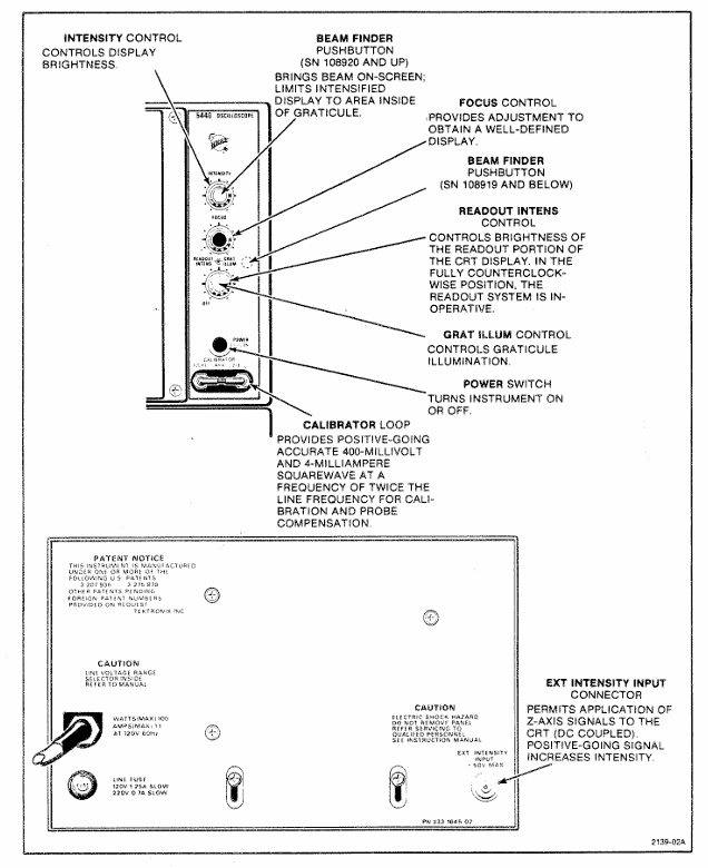
Display related: INTENSITY adjusts the brightness of the trajectory, READOUT INTENS only adjusts the brightness of the reading part (the reading system fails when counterclockwise to the bottom), FOCUS controls for clear display, and BEAM FINDER compresses the trajectory to the scale range.
Power supply and calibration: The power switch (POWER) controls the power on/off, and the internal calibrator (CALIBRATOR LOOP) provides a square wave signal with a voltage of 400mV (± 1%) and a current of 4mA (± 1%), with a frequency of twice the power supply frequency, for calibration and probe compensation.
External interface: EXT INTENSITY INPUT interface receives Z-axis modulation signals (DC coupling,+5V enhanced brightness, -5V reduced brightness, maximum safe input ± 50V, frequency range DC to 2MHz).
(2) Core functions
Display mode:
Alternate mode: The time base plugin display switch pops up and switches between the activated plugin/channel with each CRT scan, suitable for high-frequency signals.
Chop mode: When the time base plugin display switch is pressed, it electronically switches between channels at a rate of 100kHz, suitable for displaying low-frequency signals or single event phenomena.
X-Y operation: Install 5A series amplifiers or 5B series time base plugins with amplifier channels in the horizontal cabin to receive X signals, and 5A series amplifiers in the vertical cabin to receive Y signals, achieving signal comparison display.
Grating display: Both the left vertical cabin and the horizontal cabin are equipped with 5B series time base plugins. The scanning speed of the vertical cabin is slower than that of the horizontal cabin, and brightness modulation is achieved through EXT INTENSITY INPUT, which can simulate TV display.
Reading System: Only supports 5400 series plugins, displaying alphanumeric information in real-time with analog waveforms on CRT. Each plugin's reading occupies a fixed position (channel 1 is indexed at the top, channel 2 is indexed at the bottom), displaying up to 6 readings (option 3 can select 8 readings). The reading interruption waveform display is only about 20 microseconds/character.
Operation Guide
(1) First operation process (19 steps in total, with the following key steps)
Plug in preparation: Install 5A series amplifier plugs in the left/middle vertical cabin and 5B series time base plugs in the horizontal cabin.
Power connection: After confirming the operating voltage, turn off the power switch and connect a power source that meets the voltage/frequency requirements.
Initial setup:
Amplifier plugin: Display on, center position, CH1 Volts/Div set as needed, CH1 Variable Volts/Div clockwise to the end (Cal), CH1 Input Coupling set to DC, mode set to CH1.
Time base plugin: Display alternately (button pops up), center position, Main Sec/Div set to 5ms, Variable Seconds/Div clockwise to the end (Cal), Swp Mag turned off (button pops up), Main Trig Level counterclockwise to the end, trigger source selected to the left (or center, if the amplifier is in the middle compartment), coupled with Auto Trig, AC Couple,+Slope, mode set to Main Sweep.
Calibration check: Connect the probe/test line to the calibrator, adjust the trigger level to obtain stable display, check the waveform amplitude (4 divisions) and cycle (6 complete cycles, 5 cycles for 50Hz power supply), and recalibrate if abnormal.
(2) Basic measurement methods
Calculation formula/explanation for key steps of measurement type
AC peak to peak voltage: 1. The vertical plug-in input coupling is set to Gnd, and AC is set after receiving the signal; 2. Volts/Div is set to display 5-6 vertical divisions, and Variable Volts/Div is set to Cal; 3. Adjust the trigger to obtain stable display, and measure the vertical division of peak values; 4. Result=Division value × Volts/Div × Probe attenuation ratio (if any) Example: 4.6 Division value × 5V/Div=23V
DC instantaneous voltage: 1. The vertical plug-in input coupling is set to Gnd, and the trajectory is positioned to the reference line (such as the bottom part degree, negative voltage is used at the top); 2. After receiving the signal, set the DC and measure the vertical division between the reference line and the measurement point; 3. Result=division value x Volts/Div x probe attenuation ratio (if any), polarity determined by waveform position (+input and waveform is positive on the reference line) Example: 4.6 division x 2V/Div=+9.2V
Time cycle 1. Connect the signal, select AC/DC coupling, set Volts/Div to display 4 divisions; 2. Adjust the trigger to obtain stable display, set Sec/Div to 1 cycle display<8 divisions; 3. Measure the horizontal division of two points (Variable Sec/Div at Cal); 4. Result=Division value x Sec/Div Example: 5 divisions x 0.1ms/Div=0.5ms
Frequency 1. Obtain the period (T) by measuring the time period method; 2. Frequency=1/T Example: Period 0.5ms, Frequency=1/0.5ms=2kHz
Rising time (10% -90% point) 1. Connect the signal, set Volts/Div and Variable to display 5 vertical divisions; 2. Adjust the trigger to obtain stable display, set Sec/Div to 10% -90% point display<8 divisions; 3. Measure the horizontal division of two points; 4. Result=Division value x Sec/Div Example: 4 divisions x 1 μ s/Div=4 μ s
Specification parameters
1: Vertical amplifier specifications
Additional information on characteristic performance requirements
Bandwidth (6-degree reference) DC to at least 85MHz (067-0680-00 calibration fixture); DC to at least 50MHz (calibrated 5A48)-
Rise time (6 divisions reference) 7ns or less (calibrated 5A48)-
Distortion (6-degree reference) 5% or less (067-0680-00 calibration fixture); 4% or less (calibrated 5A48)-
The influence of position on distortion ± step response signal deviation does not exceed ± 5% (trajectory deviation from the center of the scale does not exceed 1 division)-
Within ± 0.5 divisions of the center of the vertical center scale-
Delay line length 140ns-
Chopping rate 50kHz (+50% -30%), conducting in 3 μ s and turning off in 2 μ s-
Alternating rate: scan every two times-
Table 2: Specifications of Horizontal Amplifier and Z-axis Amplifier
Performance requirements for amplifier type characteristics
Horizontal amplifier bandwidth DC to at least 2MHz (8-division signal reference); At least 20kHz at the low frequency end
The Z-axis amplifier inputs a voltage of+5V to switch the CRT beam from off to on; -5V switches the beam from on to off
Available frequency range DC to 2MHz
Input impedance (resistance) 10k Ω
Table 3: Power, Environment, and Physical Specifications
Category Characteristics Performance Requirements
Power input voltage (RMS) nominal 100V, 110V, 120V, 200V
Input frequency adapted to standard power frequency
Maximum 100W at 120V AC and 60Hz input power
Fuse 120V AC with 1.25A slow melting; 240V AC with 0.7A slow melting
Environmental working temperature: 0 ° C to+50 ° C
Storage temperature -40 ° C to+70 ° C
Working altitude up to 15000 feet
Storage altitude up to 50000 feet
Physical weight 25lbs (11kg)
Panel and shell anodized aluminum panel (gray vinyl coated frame), blue vinyl coated shell
Scale dial 8 × 10 divisions, 1.22cm/division, standard white internal scale line, optional black
Installation and maintenance
(1) Rack installation
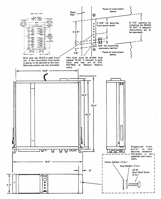
Requirement: Suitable for 19 inch standard racks (Universal, EIA, RETMA, Western Electric hole positions), with a minimum vertical space of 5-1/4 inches and an additional 1/4 inch heat dissipation space above and below; Front rail spacing ≥ 17-5/8 inches (unthreaded) or 17-3/4 inches (tapped); The gap between the rear and the rack enclosure is ≥ 2 inches.
Sliding rail installation: The sliding rail is divided into left and right components (marked LH/RH), with the fixed section installed on the front and rear rails of the rack, the chassis section pre installed with instruments, and the middle section connecting the two; During installation, it is necessary to align horizontally to avoid exchanging left and right (which may cause the safety lock to fail and cause the instrument to slide). The front panel needs to be fixed with 10-32 screws (the rack needs to correspond to the hole position).
Maintenance: The slide rail does not require lubrication, and the dark coating on the sliding parts is permanently lubricated.
(2) Plugin installation and maintenance
Installation: Align the upper and lower slots of the plug-in with the cabin guide rail, and push it into the lock; It can be plugged and unplugged with power, without filling all cabins, only installing the required measuring plugs is needed.
Calibration: After the display unit is calibrated according to the instructions, the vertical/horizontal gain is standardized. The plug-in can be interchanged between cabins without the need for readjustment, but the basic calibration of the plug-in itself needs to be checked to ensure measurement accuracy (refer to the plug-in manual).
(3) Safety regulations
Maintenance safety: Only qualified personnel are allowed to carry out repairs, and individual repairs are prohibited (emergency personnel must be provided); Live maintenance should avoid touching exposed connections/components, and disconnect the power supply before dismantling panels, welding, or replacing components.
Power safety: The power supply must meet the RMS voltage between phase lines and between phase lines and ground ≤ 250V, and the grounding conductor of the power line must be reliably grounded.
Performance check
(1) Testing equipment requirements (key equipment as follows)
Equipment Name Performance Requirements Application Scenarios
DC voltmeter range 0-200V (accuracy 0.1%); 0-3000V (accuracy 1%) low/high voltage power supply inspection and adjustment
Calibration generator amplitude calibration 10mV-1V (accuracy ± 0.25%, 1M Ω load), square wave output gain inspection and adjustment
Timing generator outputs 5ns and 10ns markers (accuracy ± 1%) for scanning timing inspection (5ns, 10ns)
5A48 amplifier plug-in bandwidth DC to 500MHz, display mode CH1 vertical/horizontal system adjustment
5B42 time base plugin scanning speed of at least 10ns/div scanning timing inspection and adjustment
(2) Key inspection items
Trajectory alignment: Horizontal trajectories are aligned with the center horizontal scale line, and vertical trajectories are aligned with the center vertical scale line, with an error of ≤ 0.1 divisions.
Geometric shape: Trajectory curvature/inclination ≤ 0.1 divisions, angle between vertical and horizontal trajectories 90 °± 0.7 °.
Vertical performance:
Gain: Input 1kHz square wave, display 5V reference signal, vertical deflection of 5 divisions ± 0.15 divisions (± 3%).
Bandwidth: Input a 50kHz sine wave, display 6 divisions, increase the frequency until the amplitude drops to 4.2 divisions, and the frequency needs to be ≥ 50MHz (5A48 plugin).
Horizontal performance:
Gain: Input 1kHz square wave, display 5V reference signal, horizontal deviation of 5 divisions ± 0.15 divisions.
Bandwidth: Input a 50kHz sine wave, display 6 divisions, increase the frequency until the amplitude drops to 4.2 divisions, and the frequency needs to be ≥ 2MHz.
Reading system: In dual track mode, readings are displayed at the top/bottom of the CRT without overlap, corresponding to Volts/Div and Sec/Div settings; When CAL controls counterclockwise rotation, the ">" symbol is displayed on the left side of the reading.
- ABB
- General Electric
- EMERSON
- Honeywell
- HIMA
- ALSTOM
- Rolls-Royce
- MOTOROLA
- Rockwell
- Siemens
- Woodward
- YOKOGAWA
- FOXBORO
- KOLLMORGEN
- MOOG
- KB
- YAMAHA
- BENDER
- TEKTRONIX
- Westinghouse
- AMAT
- AB
- XYCOM
- Yaskawa
- B&R
- Schneider
- Kongsberg
- NI
- WATLOW
- ProSoft
- SEW
- ADVANCED
- Reliance
- TRICONEX
- METSO
- MAN
- Advantest
- STUDER
- KONGSBERG
- DANAHER MOTION
- Bently
- Galil
- EATON
- MOLEX
- DEIF
- B&W
- ZYGO
- Aerotech
- DANFOSS
- Beijer
- Moxa
- Rexroth
- Johnson
- WAGO
- TOSHIBA
- BMCM
- SMC
- HITACHI
- HIRSCHMANN
- Application field
- XP POWER
- CTI
- TRICON
- STOBER
- Thinklogical
- Horner Automation
- Meggitt
- Fanuc
- Baldor
- SHINKAWA
- Other Brands
- UniOP
- KUKA
- Iba
-
 Samsung D0C-16C Digital I/O Control Module
 -
 SAMWONTECH TLC990ME-83 Multi-Channel PID Controller
 -
 SanDisk SDP3B-10 Industrial Flash Storage
 -
 SAC IOP351 Advanced Processor
 -
 SAC IOP331 Input/Output Processor Technical
 -
 Saftronics EZ6 40 Soft Starter Manual
 -
 Sagemcom 252720938AB Signal Processor
 -
 Sagemcom 252721117AC Interface Module
 -
 Sagemcom 252721013AF Controller
 -
 SAIA PCD2.W610 Analog Output Module
 -
 SAIA PCD3.R60X Flash Memory Storage Module
 -
 SAT RM3141-01-02 CM3141-01-02 System
 -
 SAT CM3142-01-03 CX3147-04 Overview
 -
 SAT CM3141-02-03 CX3149-05 Technical Manual
 -
 Sauter AVM234SF132 Valve Actuator Specs
 -
 SBS PFSK165 3BSE027778R1 Technical Specs
 -
 SBS VIPC616 91611524 VME Carrier Board
 -
 SBS PMC-HS-SERIAL Interface Module
 -
 Schenck FNT-L001 Network Terminal Guide
 -
 Schenck VEG20400 Weighing Electronics Specs
 -
 Schiele DL42N-22 Multi-Function Relay
 -
 Schiele DL22N-22 Monitoring Relay Specs
 -
 Schleicher SSY52 Safety Control Unit Manual
 -
 Schleicher UST21 Control Module
 -
 SanDisk 336A4940EZP1 Industrial SSD
 -
 Sankyo PC10021 Industrial Control Module
 -
 SANMOTION PB3A003P200 Servo Drive
 -
 Sanyo P30B04010PCKST AC Servo Motor
 -
 Sanyo STNM-DR-250B Industrial Drive Module
 -
 Sanyo STNM-DR-160B Mixed I/O Module
 -
 Sanyo PMDAA1SFC20R Servo Amplifier
 -
 Sartorius MDB-5E Precision Weighing Module
 -
 SBS VIPC616 VME-IP Carrier Board
 -
 SBS 82002070 High-Performance Control Module
 -
 SBS P2-100BT-ER Industrial Ethernet Module
 -
 SBS 82002077 Industrial Control Module
 -
 SCANLAB INTELLISCANDE14-405NM UV Laser Scan Head
 -
 SCANLAB INTELLISCANDE14-1064NM IR Laser Scan Head
 -
 SCANLAB INTELLISCANDE III14-532NM Laser Scan Head
 -
 SCHAFFNER FN3416-110-35 EMI Power Line Filter
 -
 SCHROFF MPS015 Series
 -
 SCHROFF MPS015 13100205 Power Supply
 -
 SCHROFF 3BSC690076R5 Module Review
 -
 SCHUMACHER ATCS-15 1464-0320 Review
 -
 SCHUMACHER MDIA-162 System Analysis
 -
 SCHUMACHER ATCS-15 Technical Guide
 -
 Schumacher 1442-0010H Industrial Battery Charger Module
 -
 Seagate ST3630A 3.5 Inch IDE Hard Drive
 -
 SEC PB5F-DYL Latching Relay Output Module
 -
 SEC PB5F-DYI Isolated High-Density Output Module
 -
 SEC PB5F-DY High-Density Digital Output Module
 -
 SEC PB5-DY 5-Channel Digital Output Module
 -
 SEC PB4-DYI Isolated Digital Output Module
 -
 SEC PB4-DY 4-Channel Digital Output Module
 -
 SECO B161S-E176 Control Card
 -
 SEF M21.1 Control Module
 -
 Seidel MV65WKS-CE310/22PB Driver
 -
 SEM MT30R4-37 Servo Motor
 -
 SEMIKRON SKD62/16 Rectifier Bridge
 -
 SENTRON LD63F600 Circuit Breaker
 -
 Sentry VREL-11 Voltage Relay
 -
 Servo MTS30M4-38 AC Servo Motor
 -
 Servo Module SEVO BOARO C20003/2.1 Motion Control Board
 -
 Servoland SVFH8-H3-DSP*ANI Servo Drive
 -
 Servotecnica SVT57BL03-60V Brushless Servo Motor
 -
 SES 2422 Frequency to Analog Converter
 -
 SES 2409 Thermocouple Signal Conditioner
 -
 SES 2411 Industrial Signal Conditioner
 -
 SEW MDV60A0110-5A3-4-00 11kW Drive
 -
 SEW MPB51A055-503-00 Power Unit
 -
 SEW 31C055-503-4-00 5.5kW Inverter
 -
 SEW R37DS56L Geared Motor Specs
 -
 SEW MDV 8222215.14.17 Power Board
 -
 SEW MKS51A005-503-50 MOVIKIT Controller
 -
 SEW MHD093C-058-PG0-AN Synchronous Servo Motor
 -
 SEW MDV60A0075-5A3-4-0T MOVITRAC Frequency Inverter
 -
 SEW MDS60A0150-503-4-00 MOVIAXIS Servo Drive
 -
 SEW MDF60A-0075-5A3-4-00 MOVIFIT Drive
 -
 SEW MDF60A-0022-5A3-4-00 MDX60A0075-5A3-4-00 Drive System
 -
 SEW MDF60A-0022-5A3-4-00 MOVIFIT Drive
 -
 SEW EF-014-503 Braking Resistor
 -
 SEW DFP11B 8227241.12 Interface
 -
 SEW DFP 21A PROFIBUS Interface Card
 -
 SEW 31C450-503-4-00 45kW Inverter
 -
 SEW 31C075-503-4-00 7.5kW Inverter
 -
 SEW 31C015-503-4-00 1.5kW Inverter
 -
 SEW 31C005-503-4-00 Drive Analysis
 -
 SHINKAWA VM-5G0-2 General Purpose Monitor
 -
 SHINKAWA VM-5C Shaft Eccentricity Monitor
 -
 SHINKAWA VM-5Z4 Power Supply Module
 -
 SHINKAWA VM-5P3 Phase Reference Module
 -
 SHINKAWA VM-5H3 8-Slot Monitoring Rack
 -
 SHINKAWA VM-5Y1-02 GEM Process Monitor
 -
 SHINKAWA VM-5K Dual Vibration Monitor
 -
 SHINKAWA MP-2W2 Differential Expansion Monitor
 -
 SHINBORY DENSHI HD-522 Technical Guide
 -
 SHINKAWA MP-2P1 Industrial Vibration Monitoring Module
 -
 SHINKAWA MP-2P4 Multi-Channel Vibration Monitoring Module
 -
 SHINKAWA MP-2S Vibration Monitoring Module
 -
 SHINKAWA MP-2T Magnetic Pickup
 -
 SIEBEL IPS21-24V-35AD ABB Module
 -
 SIEBEL&SCHOLL IPS21-35AD Power Supply
 -
 SIEGER 05701-A-0550 Control Unit
 -
 SIEGER 05704-A-0122 Control Card
 -
 Siemens Moore 16114-171 I/O Module
 -
 Sigmatek DNC115 Digital I/O Module
 -
 Silicon Graphics B014ANT180 Graphics Card
 -
 Silicon Graphics 030-0730-003 VGA Graphics Module
 -
 SIMCO FMX-003 Electrostatic Field Meter
 -
 SHINKAWA MP-2S Vibration Monitoring Module
 -
 SINANO SE04-10WA Servo Driver Info
 -
 SIS AI3281 Analog Input Module
 -
 SIS CM01 Communication Module
 -
 SIS MC01 Main Controller Module
 -
 SIS DO3201 Digital Output Module
 -
 SIS DI3201 Digital Input Module
 -
 SIS BI01 Bridge Input Module
 -
 SIS PM01 Power Monitor Module
 -
 SKIIP 39AC12T4V1 IGBT Power Module
 -
 SLIMPAK 10923H5A Isolated DC-DC Converter
 -
 SLIMPAK G468-0001 Isolated Signal Conditioner
 -
 SLIMPAK G408-0001 DC-DC Converter
 -
 SLO-SYN M063-LE-507E Hybrid Stepper Motor
 -
 SMC VQ1-LPF04+VQ1100N-5 Valve Assembly
 -
 SMC INR-244-203B Technical Overview
 -
 SMC INR-244-97B-B-X5 Cooling System Info
 -
 SMC MHY2-10D2 Air Gripper
 -
 SNAP CB:2F:DA 8/4MB Memory Module


