TOSHIBA V200 series programmable logic controller
Target audience: Qualified Person operators are required, who possess electrical equipment installation/maintenance skills and have received safety training (in compliance with NFPA 70E standards).
Software Configuration and Programming
4.1 OIL DS software installation
System requirements:
Operating systems Windows 2000 (SP4), XP (SP2), Vista
Processor ≥ 800MHz (Vista requires ≥ 1GHz)
Memory ≥ 256MB (Vista requires ≥ 1GB)
Hard disk space of 800MB (including 200MB. NET Framework)
Display resolution 1024 × 768 (16 bit high color)
Installation steps:
Run Setup. exe and select the installation path (default C: Program Files OIL DS).
Wait for the installation to complete and start the software through "Start → Program → OIL DS".
When uninstalling, execute through "Start → Program → OIL DS → Uninstall OIL DS".
4.2 Ladder diagram programming
Core process:
New project: Select V200 model (such as GPU288 * 3S), configure project name and storage path.
Define Tag Database: Assign I/O addresses (such as X0000 corresponding to digital input 1) and register types (input X/output Y/configuration MW).
Edit ladder diagram: Drag and drop "normally open contact (NO)", "coil", "function block (such as MOV-W)" to construct logic, supporting subroutines and interrupt programs.
Compile and Download: Press F9 to compile (if there are no errors, it will display "Compilation Successful"), and download it to the PLC via USB/RS485.
Program type:
Main program: It runs in a loop during normal operation and needs to end with the "END" instruction.
Subroutine: Called with the "CALL" instruction and returned with the "RET" instruction.
Interrupt program: Timer interrupt (5-1000ms), I/O interrupt (triggered by high-speed counting), must end with the "IRET" instruction.

Detailed explanation of special I/O functions
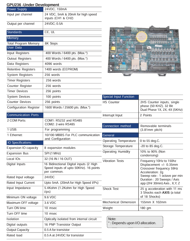
5.1 High speed counter
Function type:
Type Input Channel Maximum Frequency Counting Range Application Scenarios
Single phase counter 2-channel (X000/X001) 50kHz 0~4294967295 (32-bit) pulse counting (such as encoder)
Single phase speed counter 2-channel (X000/X001) 50kHz 0~4294967295 (32-bit) speed measurement (fixed sampling time)
Orthogonal biphasic counter 1 channel (X000=phase A, X001=phase B) 5kHz 0~4294967295 (32-bit) bidirectional counting (such as motor forward and reverse rotation)
Configuration register: Select the function mode through MW10 (high-speed input configuration register), such as "MW10=0x0010" to enable the single-phase counter.
5.2 Pulse/PWM output
Pulse output:
Channel: 1 channel (Y0=CW/PLS, Y1=CW/DIR).
Frequency range: 50~5000Hz, supports positive and negative frequencies (corresponding to positive and negative reversals).
Configuration: Set MW11 (pulse output configuration register) to "0x0001" enabled, and set the frequency for MW22/MW23.
PWM output:
Channel: 1 channel (Y0).
Parameters: frequency 50~5000Hz, duty cycle 0~100% (1% step size).
Configuration: MW11 is set to "0x0000" enabled, and MW24/MW25 is set to duty cycle.
5.3 Interrupt Input
Channel: 2 channels (X001=Interrupt 1, X002=Interrupt 2).
Trigger method: Rising edge (OFF → ON) or falling edge (ON → OFF), configured through MW10's Bit4/Bit5.
Response time: Interrupt signal ON/OFF pulse width ≥ 100 μ s, ensuring stable recognition of PLC.
Troubleshooting and Maintenance
6.1 Troubleshooting process
Power failure (PWR light not on):
Check the power wiring: whether the terminals are loose and whether the voltage is 24VDC ± 15%.
Remove the expansion module: If the PWR light is restored, troubleshoot the expansion module.
Check internal power supply: If it still doesn't light up, replace the PLC host.
CPU malfunction (RUN light not on):
Check the mode switch: whether it is in the "RUN" position, switch to "RUN" and retry.
Check the ERR light: If the ERR light is on, read the fault code through OIL DS (such as "WDT Error" indicating watchdog timeout).
Re download firmware: If the RUN/ERR lights flash simultaneously, the firmware is damaged and needs to be re downloaded.
Input/output fault (abnormal I/O status):
Check the wiring: Check if the terminal screws are loose and if the wires are damaged.
Monitoring I/O status: Check the X/Y status through the "Monitor" function of OIL DS to determine whether it is a hardware or program issue.
Replace module: If one of the I/O channels is consistently abnormal, replace the corresponding expansion module.
6.2 Maintenance Standards
Daily inspection (daily):
Appearance: The LED status is normal (PWR is constantly on, flashing when RUN is running), and there is no abnormal sound/odor.
Environment: Temperature 0~55 ℃, humidity 20%~90%, no dust accumulation.
Regular inspection (every 6 months):
Cleaning: Use compressed air (≤ 0.3MPa) to clean the dust from the cooling fins and ventilation openings.
Wiring: Tighten all terminal screws (to the specified torque) and check the insulation layer of the wire.
Insulation test: After power failure, use a 500V megohmmeter to test the insulation resistance of the main circuit to ground to be ≥ 1M Ω.
Suggestions for spare parts:
Spare parts names, suggested quantities, and notes
Minimize system downtime with one V200 CPU
1 commonly used I/O module each, such as GDI216S (digital input), GAD208S (analog input)
- ABB
- General Electric
- EMERSON
- Honeywell
- HIMA
- ALSTOM
- Rolls-Royce
- MOTOROLA
- Rockwell
- Siemens
- Woodward
- YOKOGAWA
- FOXBORO
- KOLLMORGEN
- MOOG
- KB
- YAMAHA
- BENDER
- TEKTRONIX
- Westinghouse
- AMAT
- AB
- XYCOM
- Yaskawa
- B&R
- Schneider
- Kongsberg
- NI
- WATLOW
- ProSoft
- SEW
- ADVANCED
- Reliance
- TRICONEX
- METSO
- MAN
- Advantest
- STUDER
- KONGSBERG
- DANAHER MOTION
- Bently
- Galil
- EATON
- MOLEX
- DEIF
- B&W
- ZYGO
- Aerotech
- DANFOSS
- Beijer
- Moxa
- Rexroth
- Johnson
- WAGO
- TOSHIBA
- BMCM
- SMC
- HITACHI
- HIRSCHMANN
- Application field
- XP POWER
- CTI
- TRICON
- STOBER
- Thinklogical
- Horner Automation
- Meggitt
- Fanuc
- Baldor
- SHINKAWA
- Other Brands


