YOKOGAWA WT1801R series precision power analyzer communication interface
Composite instruction: Instrument specific hierarchical instruction, separated by: (e.g. DISPlay: MODE NUMeric to set display mode to numerical display).
Simple instruction: Non hierarchical independent instruction (such as HOLD to set data hold).
Data format: Supports decimal (NR1/NR2/NR3), physical quantities (with units, such as 100V), registers (binary/octal/hexadecimal), strings (user-defined, such as file names), and other formats.
2. Core instruction grouping and functions
Chapter 5 of the document provides a detailed list of 23 instruction groups, covering scenarios such as interface control, display settings, data storage, measurement and calculation. The key instruction groups are as follows:
Instruction group core instruction example function description
COMMunicate Group :COMMunicate:REMote ON
: Communicate: READer OFF controls remote/local mode, sets response with header information
DISPlay Group :DISPlay:MODE WAVE
DISPlay: WAVE: TDIV 5MS Set display mode (waveform/value/trend), adjust waveform timeline scale
FILE Group :FILE:SAVE:NUMeric "DATA1"
: FILE: LOAD: SETup "SET1" saves numerical data to a file, loads instrument settings file
MEASure Group :MEASure:AVERaging:STATE ON
MEASure: FUNCtion1: EXPResolution "URMS (E1)" Enable data averaging function and define user-defined measurement functions
NUMeric Group :NUMeric[:NORMal]:VALue?
NUMeric: FORM ASCII queries numerical measurement data, sets data output format (ASCII/FLOAT)
STORe Group :STORe:START
: STORe: FILE: CONVert: EXECUTE "STR1" Start storing data and convert stored data to CSV format
Common Command *IDN?
*OPC? Query instrument identification (model/serial number), query operation completion status
3. Synchronization and status reporting
Synchronization mechanism: through * WAI (waiting for operation completion),: Communicate: WAIT (waiting for specified event), * OPC? (Operation completion query) Avoid instruction execution conflicts and ensure data consistency.
Status report: includes status bytes, standard event registers, extended event registers, and error queues, supported through: Status: ERRor? Query error codes and messages through * STB? Query status bytes to help locate communication or operational anomalies.

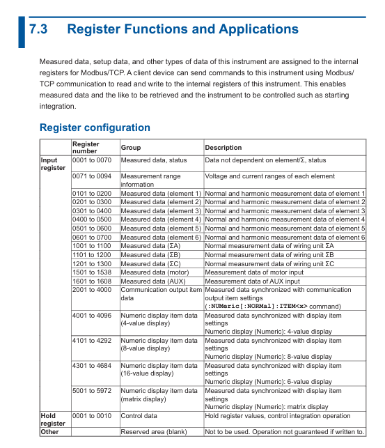
Modbus/TCP communication (extended functionality)
Function Overview: Supports Modbus/TCP protocol, can communicate with client devices (such as PLC, SCADA systems), and achieve register read/write and data interaction.
Register configuration: Chapter 7 of the document provides detailed definitions of register addresses and functions, covering measurement data, instrument status, configuration parameters, etc. It supports reading real-time data such as voltage, current, power, etc. through Modbus commands.
Communication process: The client needs to connect to the instrument's IP address and port (default 502) through TCP, and send Modbus function codes (such as 03H read hold registers) to achieve data exchange.
Precautions and Compatibility
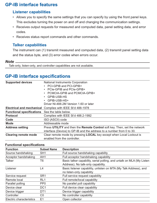
Interface exclusivity: Ethernet, USB, and GP-IB interfaces cannot be used simultaneously and need to be manually switched or specified as a unique active interface through commands to avoid command conflicts.
Driver and library dependencies: USB and Ethernet interfaces require the installation of Yokogawa Communication Library (TMCTL) and drivers, and only support Windows systems, not compatible with third-party drivers.
Cable and Connection: GP-IB requires cables that comply with IEEE standards, Ethernet needs to be connected through a hub/router (cross wiring is not supported), and USB needs to be plugged in and unplugged after the instrument is turned on and stabilized.
Legacy compatibility: Chapter 8 of the document provides instructions for compatibility with WT1600, WT1800, and WT1800E series legacy instruments, facilitating smooth migration for existing users.

- ABB
- General Electric
- EMERSON
- Honeywell
- HIMA
- ALSTOM
- Rolls-Royce
- MOTOROLA
- Rockwell
- Siemens
- Woodward
- YOKOGAWA
- FOXBORO
- KOLLMORGEN
- MOOG
- KB
- YAMAHA
- BENDER
- TEKTRONIX
- Westinghouse
- AMAT
- AB
- XYCOM
- Yaskawa
- B&R
- Schneider
- Kongsberg
- NI
- WATLOW
- ProSoft
- SEW
- ADVANCED
- Reliance
- TRICONEX
- METSO
- MAN
- Advantest
- STUDER
- KONGSBERG
- DANAHER MOTION
- Bently
- Galil
- EATON
- MOLEX
- DEIF
- B&W
- ZYGO
- Aerotech
- DANFOSS
- Beijer
- Moxa
- Rexroth
- Johnson
- WAGO
- TOSHIBA
- BMCM
- SMC
- HITACHI
- HIRSCHMANN
- Application field
- XP POWER
- CTI
- TRICON
- STOBER
- Thinklogical
- Horner Automation
- Meggitt
- Fanuc
- Baldor
- SHINKAWA
- Other Brands


