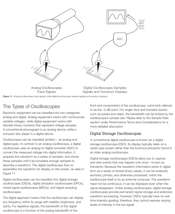
Tektronix XYZs of Oscilloscopes
Mixed signal oscilloscope (MSO) combined with DPO performance and 16 channel logic analyzer to simultaneously observe analog and digital signals, supporting protocol decoding (I2C/CAN, etc.) and digital circuit debugging (verifying the correlation between logic state and analog waveform)
Digital sampling oscilloscope first samples and then amplifies (sampling bridge → amplification) with high bandwidth (up to 80GHz), limited dynamic range (1Vp-p), safe input voltage of 3V, measurement frequency exceeding the oscilloscope sampling rate for repetitive signals (such as high-speed timing)
Oscilloscope Systems and Controls
(1) Vertical System and Control
Core functions: Adjust the vertical position and scaling of waveforms, set signal coupling and bandwidth.
Key controls:
Position and volts/div: volts/div is the scaling factor, for example: 5V/div x 8 vertical partition=40V maximum display voltage; Combined with probe attenuation (10X probe needs to be divided by 10).
Input coupling: DC (display full signal), AC (block DC, center signal), GND (disconnect input, display 0V line).
Bandwidth limitation/enhancement: Bandwidth limitation reduces noise, while bandwidth enhancement (DSP filtering) expands bandwidth and improves phase linearity.
(2) Horizontal System and Control
Core function: Control signal acquisition (sampling mode, sampling rate) and waveform horizontal position, scaling.
Key controls and concepts:
Sampling mode:
Sampling mode: 1 sampling point=1 waveform point.
Peak detection mode: Save the maximum/minimum values within 2 waveform intervals to capture fast transients (such as narrow pulses).
High resolution (Hi Res) mode: averaging multiple sampling points to reduce noise, suitable for a single event.
Envelope mode: displays the range of signal variation based on the maximum/minimum values collected multiple times.
Average mode: Average the waveform points collected multiple times, reduce noise, and repeat the signal.
Sampling method:
Real time sampling: Collect enough points in one scan, suitable for signals with a frequency<1/2 of the oscilloscope's maximum sampling rate, and the only method to capture a single transient.
Equivalent time sampling: Multiple scans capture repeated signal segments (random: sampling clock is asynchronous with trigger, supports pre trigger; sequential: delay increment Δ t per trigger, high time resolution), suitable for frequency oversampling rate of repeated signals.
Position and Sec/div: Sec/div is the time base, for example: 1ms/div x 10 horizontal partitions=10ms total display time.
Other: Time base selection (main time base/delay time base), scaling/shifting, searching (finding specific events), XY mode (X-axis is the signal rather than time, measuring phase difference).
(3) Trigger system and control
Core function: Synchronize horizontal scanning, stabilize repetitive waveforms or capture single waveforms.
Key controls and types:
Trigger position: The digital oscilloscope supports pre triggering (observing events before triggering), while the analog oscilloscope does not (except for a few delay lines).
Trigger level and slope: The level is the trigger voltage threshold, and the slope is the rising edge (positive) or falling edge (negative).
Trigger mode: Normal mode (scanning only when the signal reaches the threshold, black screen/freeze when there is no signal), Automatic mode (timer triggered when there is no trigger, ensuring display).
Trigger coupling: AC/DC/GND, and high-frequency/low-frequency/noise suppression (reducing false triggering).
Trigger suppression: After triggering, there is a "blind period" to avoid accidentally triggering complex waveforms.
Advanced triggers: burr trigger (capturing pulse width exceeding limit), pulse width trigger (capturing pulse width exceeding limit), establish hold time trigger (capturing timing violations), serial/parallel protocol trigger (such as I2C/CAN, parallel bus), etc.
(4) Display system and other controls
Display system: scale lines (8 × 10 or 10 × 10 partitions, including primary and secondary partitions), displaying volts/div and sec/div parameters.
Other controls: mathematical operations (addition, subtraction, multiplication, division, integration, FFT), digital timing and state acquisition (MSO digital channel, timing acquisition: fixed sampling rate; Status collection: clock definition of valid status.

Complete Measurement Systems (Probes)
(1) Probe type and characteristics
Probe type, core characteristics, and precautions
Passive probe universal, low cost, 10X attenuation reduces circuit load, 1X no attenuation 10X probe requires compensation (balance probe and oscilloscope electrical characteristics); 1X is susceptible to interference and suitable for low-speed, low amplitude signals
Active and differential probes contain dedicated ICs, high fidelity, low load, suitable for high speed (such as LVDS), and differential signals require DC power supply (some through oscilloscope interfaces); Can simultaneously measure differential, single ended, and common mode signals
Logic probe MSO specific, 2 8-channel pods, rechecked grounded, low capacitance load (reduces signal distortion), blue coaxial labeled first channel, universal grounding compatible with custom connections
- ABB
- General Electric
- EMERSON
- Honeywell
- HIMA
- ALSTOM
- Rolls-Royce
- MOTOROLA
- Rockwell
- Siemens
- Woodward
- YOKOGAWA
- FOXBORO
- KOLLMORGEN
- MOOG
- KB
- YAMAHA
- BENDER
- TEKTRONIX
- Westinghouse
- AMAT
- AB
- XYCOM
- Yaskawa
- B&R
- Schneider
- Kongsberg
- NI
- WATLOW
- ProSoft
- SEW
- ADVANCED
- Reliance
- TRICONEX
- METSO
- MAN
- Advantest
- STUDER
- KONGSBERG
- DANAHER MOTION
- Bently
- Galil
- EATON
- MOLEX
- Triconex
- DEIF
- B&W
- ZYGO
- Aerotech
- DANFOSS
- Beijer
- Moxa
- Rexroth
- Johnson
- WAGO
- TOSHIBA
- BMCM
- SMC
- HITACHI
- HIRSCHMANN
- Application field
- XP POWER
- CTI
- TRICON
- STOBER
- Thinklogical
- Horner Automation
- Meggitt
- Fanuc
- Baldor


