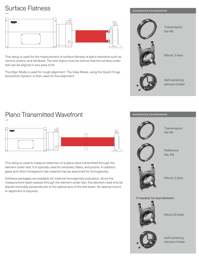
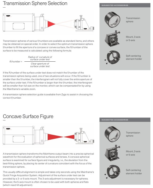
Zygo’s Guide to Typical Interferometer Setups
Clarify the correspondence between "measurement requirements → configuration plan" (such as transmission plane for planar measurement and dedicated optical components for non spherical measurement);
Master the construction process of different configurations (such as optical alignment, mechanical fixation, software debugging);
Avoid configuration errors (such as incompatible accessories, environmental interference causing accuracy deviation), and ensure that the measurement system meets the design specifications.
Zygo’s Guide to Typical Interferometer Setups
Core positioning and applicable scenarios
1. Positioning and Value
This manual should be an authoritative reference for the scenario based configuration of Zygo interferometers, with the core goal of helping users:
Clarify the correspondence between "measurement requirements → configuration plan" (such as transmission plane for planar measurement and dedicated optical components for non spherical measurement);
Master the construction process of different configurations (such as optical alignment, mechanical fixation, software debugging);
Avoid configuration errors (such as incompatible accessories, environmental interference causing accuracy deviation), and ensure that the measurement system meets the design specifications.
2. Applicable interferometer host range
Based on the Zygo interferometer product line, the core host models and adaptation scenarios covered in the manual are speculated as follows:
Key Configuration Points for the Core Application Fields of the Interferometer Series
GPI series (such as GPI XP, GPI Pro) large aperture optical components (4-18 inches): flat mirrors, spherical lenses, prism large-sized optical accessories, heavy-duty stages, vibration isolation systems
VeriFire series (such as VeriFire MST, VeriFire Sphere) high-precision wavefront analysis, non spherical measurement: optical lens, laser resonant cavity high-resolution imaging component, non spherical dedicated transmission element, dynamic calibration module
NewView series (such as NewView 5000, NewView 7000) micro morphology measurement: MEMS devices, microstructure surfaces, step height high magnification microscope objectives, white light scanning module, precision Z-axis drive

Speculative core content framework
1. Classification of typical configuration schemes (by measurement object)
The manual is likely divided into chapters based on the type of component being tested, providing targeted configuration cases. Each case includes a component list, technical parameters, construction steps, and accuracy verification. It is speculated that the core solution is as follows:
(1) Measurement configuration of planar components (such as glass plates, flat mirrors)
Core component list:
Host: GPI Pro (8-inch caliber);
Optical accessories: 8-inch transmission plane (TF, flatness ≤ 0.02 λ RMS, λ=632.8nm), laser collimator;
Mechanical accessories: manual fine adjustment stage (X/Y axis accuracy ± 1 μ m), passive isolation stage (isolating 1-10Hz vibration);
Software: MetroPro 9.0 (loads the "Plane Measurement" application module).
Key configuration points:
Optical alignment: The center of the transmission plane is coaxial with the optical axis of the interferometer (deviation ≤ 0.1mm), verified by MetroPro's "center calibration" function;
Environmental control: temperature 20 ± 0.5 ℃ (to avoid material thermal deformation), humidity 40% -60% (to prevent condensation on optical surfaces);
Accuracy index: Flatness measurement repeatability ≤ 0.05nm RMS, measurement range covering 4-8 inch components.
(2) Spherical component measurement configuration (such as convex/concave spherical lenses)
Core component list:
Host: VeriFire MST;
Optical accessories: Transmitting sphere (TS, curvature radius matching the tested object, such as 100mm), polarizer (optimized fringe contrast);
Mechanical components: programmable stage (X/Y/Z axis repeat positioning accuracy ± 0.5 μ m), spherical centering fixture;
Software: MetroPro "Spherical Analysis" module (supports calculation of curvature radius and surface shape error).
Key configuration points:
Selection of Transmitting Spherical Surface: Match the "curvature radius+aperture" of the tested spherical surface (such as selecting the TS-100 model for a 100mm curvature radius lens);
Auto null: Reduce tilt/eccentricity errors in spherical measurements through software calibration;
Accuracy index: curvature radius measurement error ≤ 0.1%, surface shape error repeatability ≤ 0.03 λ RMS.

(3) Microscopic morphology measurement configuration (such as MEMS devices, microstructures)
Core component list:
Host: NewView 7000;
Optical accessories: 50X Mirau objective lens (NA=0.4, working distance 0.3mm), white light scanning module;
Mechanical components: Nano level Z-axis drive (stroke 100 μ m, accuracy ± 0.01 μ m), vacuum suction cup fixture (fixing small components);
Software: MetroPro "roughness analysis" module (supporting Ra, RMS, Rz calculations).
Key configuration points:
Objective calibration: Use Zygo standard calibration parts (such as 1 μ m step height standard parts) to calibrate the lateral resolution (such as 50X objective → 2.5 μ m/pixel);
Scanning parameters: Set the scanning length according to the height of the microstructure (such as selecting a scanning length of 20 μ m for a 10 μ m microstructure);
Accuracy index: The measurement error of step height is ≤ 0.05 μ m, and the repeatability of roughness measurement is ≤ 0.1nm Ra.
(4) Online measurement configuration for production lines (such as automotive glass, consumer electronics lenses)
Core component list:
- ABB
- General Electric
- EMERSON
- Honeywell
- HIMA
- ALSTOM
- Rolls-Royce
- MOTOROLA
- Rockwell
- Siemens
- Woodward
- YOKOGAWA
- FOXBORO
- KOLLMORGEN
- MOOG
- KB
- YAMAHA
- BENDER
- TEKTRONIX
- Westinghouse
- AMAT
- AB
- XYCOM
- Yaskawa
- B&R
- Schneider
- Kongsberg
- NI
- WATLOW
- ProSoft
- SEW
- ADVANCED
- Reliance
- TRICONEX
- METSO
- MAN
- Advantest
- STUDER
- KONGSBERG
- DANAHER MOTION
- Bently
- Galil
- EATON
- MOLEX
- DEIF
- B&W
- ZYGO
- Aerotech
- DANFOSS
- Beijer
- Moxa
- Rexroth
- Johnson
- WAGO
- TOSHIBA
- BMCM
- SMC
- HITACHI
- HIRSCHMANN
- Application field
- XP POWER
- CTI
- TRICON
- STOBER
- Thinklogical
- Horner Automation
- Meggitt
- Fanuc
- Baldor
- SHINKAWA
- Other Brands


