
Allen Bradley 150 Series SMC Dialog Plus Controller
Installation specifications
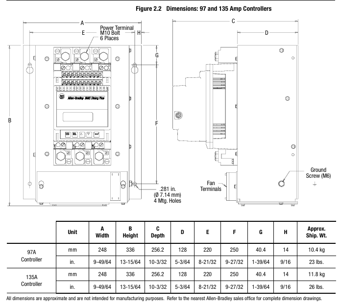
The radiator fins need to be installed vertically, with at least 15cm of space reserved above and below to ensure air circulation; Grounding should be connected to the controller's dedicated grounding screw/terminal post, in accordance with the IEC 5019 grounding identification standard.
(3) Wiring: Power and Control Circuit Configuration
Power wiring
The input (L1/L2/L3) is connected to the power grid, and the output (T1/T2/T3) is connected to the motor. Different current levels of terminals are compatible with different wire specifications (such as 24-54A supporting 2.5-25mm ² wires, 1000A supporting 50-240mm ² wires), and the terminals need to be tightened according to the torque specified in the manual (such as 0.8N · m for 2.5-6mm ² wires).
Suggest installing a fast current limiting fuse (such as 24A with 170M 3610-63) to protect the SCR from overcurrent damage; The power factor correction capacitor needs to be installed on the input side of the controller to avoid damage to the SCR caused by capacitor discharge.
Control wiring
The control power supply supports 100-240V AC (± 15%/± 10%) or 24V AC/DC (± 15%/± 10%), and requires separate connection to terminals 11/12. The control module has a power consumption of 40VA, and the cooling fan requires additional power supply (such as 45VA for 97A fans).
Control terminal functions: terminals 13 (enable), 16 (start), 17 (stop), 19-20 (auxiliary contacts 1&2, Form C, can be set to "normal/rated speed"), 29-30 (auxiliary contact 3, can be set to "normal/fault"), some terminals (such as 25-28) are used to connect converter modules or communication modules.
Typical wiring scheme: Provides 12 scenario wiring diagrams, including standard control, dual ramp start, bypass operation, reverse control, manual automatic (SCANPort) control, etc. If the bypass configuration requires the use of an 825 converter module to maintain current monitoring and avoid loss of protection function after controller bypass.
(4) Programming: Parameter Setting and Operation
Programming interface: Operated through the built-in 2-line 16 character backlit LCD and 4 keys (ESC/SEL/up and down arrows), the menu is divided into 4 levels (operation layer → mode layer → group layer → parameter layer), supports password protection (prevents unauthorized modification) and "search" mode (only displays non default parameters).
Core parameter group
Basic Setup: Configure startup mode, ramp time, current limit, energy-saving mode, auxiliary contact function, etc., suitable for fast startup.
Advanced Setup: includes dual ramp parameters, overvoltage/undervoltage thresholds, voltage imbalance protection, phase balance, hourly startup times, etc., suitable for complex scenarios.
Calibrate: Input the motor nameplate data (rated current, service factor, motor code, etc.), and use a true RMS clamp meter (accuracy ± 1%) to calibrate the current measurement and ensure the accuracy of the protection function.
Parameter storage: Parameters are stored in RAM by default (lost during power failure) and need to be manually saved to EEPROM (non-volatile). It supports restoring factory default values.
(5) Diagnosis and Troubleshooting: Problem Localization and Resolution
Fault display: The first row of the LCD displays the fault type (such as "OVERLOAD"), the second row displays the fault code (such as "F7"), and the fault buffer stores the last 5 fault records.
Common faults and solutions
Overload (F7): Check if the motor load is too large, if the overload level matches the motor, and if the FLC parameters are entered correctly.
Phase loss (F1-F3): Check if the power grid incoming line and motor wiring are loose, and if the fuse is blown.
SCR open circuit (F23-F25): Measure the resistance between the incoming and outgoing lines of the power module (normally>10k Ω). If there is a short circuit, replace the power module.
Communication Failure (F21): Check if the human-machine interface or communication module connected to SCANPort is disconnected, and if the Logic Mask parameter is set to 4 (enabling communication control).
Maintenance operation: When disassembling the control module, power off first, mark the wires, and then loosen the fixing screws to avoid bending the interface pins; The resistance inspection of the power module requires the use of an ohmmeter to measure the feedback resistance, gate resistance, and thermistor. If they do not meet the standards, the module needs to be replaced.
(6) Serial Communication: Remote Control and Data Interaction
Communication interface: SCANPort is standard and can be connected to 1201 human-machine interface module (programming, start stop control) or 1203 communication module (supporting protocols such as Remote I/O, DeviceNet, DH-485, etc.).
Control Enable: Parameter 85 (Logic Mask) needs to be set to 4 to enable remote control; PLC can send start stop, fault reset, option commands (such as pump stop), receive controller status (running, fault, rated speed) and metering data (current, power).
Communication example: Provide ladder diagram program examples for controllers such as SLC 500 and PLC 5, such as implementing block transfer (BTW/BTR) through Remote I/O, reading motor current, power and other parameters, or performing explicit message transmission through DeviceNet (such as reading fault codes).
- OMRON
- ABB
- General Electric
- EMERSON
- Honeywell
- HIMA
- ALSTOM
- Rolls-Royce
- MOTOROLA
- Rockwell
- Siemens
- Woodward
- YOKOGAWA
- FOXBORO
- KOLLMORGEN
- MOOG
- KB
- YAMAHA
- BENDER
- TEKTRONIX
- Westinghouse
- AMAT
- AB
- XYCOM
- Yaskawa
- B&R
- Schneider
- KONGSBERG
- NI
- WATLOW
- ProSoft
- SEW
- ADVANCED
- Reliance
- TRICONEX
- METSO
- MAN
- Advantest
- STUDER
- DANAHER MOTION
- Bently
- Galil
- EATON
- MOLEX
- DEIF
- B&W
- ZYGO
- Aerotech
- DANFOSS
- Beijer
- Moxa
- Rexroth
- Johnson
- WAGO
- TOSHIBA
- BMCM
- SMC
- HITACHI
- HIRSCHMANN
- Application field
- XP POWER
- CTI
- TRICON
- STOBER
- Thinklogical
- Horner Automation
- Meggitt
- Fanuc
- Baldor
- SHINKAWA
- Other Brands
- UniOP
- KUKA
- Iba
- Beckhoff
-
 Basler D90 96801 100 PCB Card
 -
 Basler XR2002F Voltage Regulator (110 VAC, 48-480 Hz)
 -
 Basler SR8A-2B14B3A Regulator
 -
 Basler 9561500100 Module
 -
 Basler DECS-400 BE1-11 System
 -
 Basler DECS-100-B15 Excitation Control
 -
 Basler SCP 210 Frequency Controller
 -
 Basler SR4A-2B15B3A Static Voltage Regulator
 -
 Basler BE1-32R Power Relay
 -
 Basler PIA2400-17GM Power Interface Adapter
 -
 Basler MVC 232 Manual Voltage Control Module
 -
 Basler SSR 32-12 Static Voltage Regulator
 -
 Basler 5MW AVR Generator Voltage Regulator
 -
 Basler VR63-4B Voltage Regulator
 -
 Basler DECS-100-A05 AVR for Engine Generator
 -
 Basler DECS-100-B15 Automatic Voltage Regulator
 -
 Basler BE1-32R Directional Power Relay
 -
 Basler BE1-87B Differential Relay
 -
 Basler UFOV 260A Protective Module
 -
 Basler 9-2614-02-100 PCB Rev M
 -
Basler DECS-100-B15 Digital AVR
-
 Basler 9284900103 PS DECS-400N
 -
 Basler D4N3H1U Intertie Protection
 -
 Basler DECS-100-B15 A15 AVR
 -
 Basler KR4F Voltage Regulator
 -
 Basler BE26434 T14 Transformer
 -
 Basler SR8A-2B15B3A Regulator
 -
 Westinghouse 774B472A12 AR Relay
 -
Basler DECS-100-B15 AVR
-
Basler XR2002F Regulator 110V
-
Basler SR125-E Static Regulator
-
 Basler SSR 125-12 Regulator
 -
 Basler MOC2599 Motor Pot
 -
 Basler BE1-DFPR Feeder Relay
 -
 Basler CBS 305 Current Boost
 -
 Basler BE1-25 AutoSync
 -
 Basler MVC 300 Voltage Control
 -
 Basler BE3-25A AutoSync
 -
 Basler KR7FF Static Regulator
 -
 Basler 90-49000-100 Regulator
 -
 Basler 880 kVA Dry Type Transformer Specs
 -
 Basler Electric BE1-25 Sync-Check Relay Specs
 -
 Basler SSR 125-12 Voltage Regulator Specs
 -
 Basler Electric BE1-851 Overcurrent Relay Review
 -
Basler Electric 149D930G02 Control Sub-Assembly
-
 Basler Electric BE1-81O/UT Frequency Relay Specs
 -
 Basler Electric BE1-51/27C Overcurrent Relay
 -
 Basler Electric 149D956G02 Industrial Component
 -
Basler Electric BE1-51A Overcurrent Relay Specs
-
 Basler Electric BE1-40Q Loss of Excitation Relay
 -
 Basler DECS-200 Excitation Control System
 -
 Basler DECS-200 Voltage Regulator 56-277V AC / 125V DC
 -
Basler BE1-87T Transformer Differential Relay
-
 Basler RDP-110-S1 Protection Relay
 -
 Basler BE1-700V Digital Protective Relay
 -
 Basler BE1-951 Overcurrent Protection System
 -
 Basler DECS-300 Digital Excitation Control
 -
 Basler DECS-200 Digital Excitation Control
 -
 Basler DECS-200-1C Excitation Control System
 -
Basler DECS-200-1L Digital Excitation Control
-
 Basler Electric BE1-GPS Generator Protection System
 -
Basler Electric DECS-200-1C Digital Excitation Controller
-
 Basler Electric DECS125-15 Excitation Control with Power Module
 -
 Basler Electric BE1-87G Differential Relay
 -
 Basler Electric BE1-11 Protection System I5A3M2P2N0EA00
 -
Basler Electric DECS-200-1C Excitation Control System
-
Basler Electric BE1-11g Generator Protection Relay
-
Basler Electric DECS 125-15-B2C1 V2.0.9 Excitation Control
-
 Basler Electric BE1-81O/UT3ED1JA7N2F Frequency Relay
 -
Basler Electric BE1-81O/UT3EE1YB7N1F Frequency Relay
-
 Basler Electric DECS-200-1L Digital Excitation Control System
 -
Basler DECS125-15-B2C1 Excitation Control
-
 Basler 9507900205 SSR Retrofit Voltage Regulator
 -
 Basler BE2000E Digital Voltage Regulator
 -
 Basler BE1-GPS Generator Protection System
 -
Basler DECS-250-CN1CN1N Digital Excitation Control
-
 Basler DGC-2020 Genset Controller
 -
 Basler BE1-81O UT3ED1LA7N0F Frequency Relay (Variant)
 -
 Basler BE1-81O UT3EE1YA9S0F Frequency Relay (Variant)
 -
Basler BE1-81O Over/Under Frequency Relay
-
Basler DECS125-15 Digital Excitation Control
-
Basler Electric BE1-951 Overcurrent Protection System
-
 Basler Electric BE1-700V Digital Protective Relay
 -
 Basler Electric APR63-5 Automatic Voltage Regulator
 -
Basler Electric BE1-851 Overcurrent Protection System
-
Basler Electric DECS-250-LN1SN1N Excitation Control
-
 Basler Electric BE1-87T Transformer Differential Relay
 -
Basler Electric DECS-200-1L Excitation Control System
-
 Basler Electric 9310300100 DECS-300 Excitation Control
 -
 Basler Electric SSE-N 125-4.5KW Shunt Exciter Regulator
 -
 Basler Electric DGC-2020HD-5NS1DNSBA Genset Controller
 -
Basler Electric BE1-81-O/UT3EE1JB7N1F Frequency Relay
-
Basler Electric BE1-81T1EE1WA0N1F Frequency Relay
-
 Basler Electric BE1-25M1EA6PN5R1F Sync-Check Relay
 -
 Basler Electric BE1-GPS Generator Protection System
 -
Basler Electric DECS-250-LN1SN1N Excitation Control Rev V
-
 Basler Electric DECS-250-CN2CN1N Excitation Control
 -
Basler Electric BE1-50/51B-207 Overcurrent Relay
-
Basler Electric DECS-300-C0N0 Excitation Control System
-
Basler Electric DECS-200 Digital Excitation Control System
-
Basler Electric DECS-250-LN1CN1N Excitation Unit
-
Basler Electric DECS-250 LN2SA1D Excitation Unit Specs
-
Basler Electric BE1-87T Transformer Relay Review
-
Basler Electric BE1-11 Protection System
-
Basler Electric BE1-GPS100-E4N1H1N Protection System
-
 Allen-Bradley 442G-MABH-R Safety Module
 -
 Beckhoff CX1030-0111 PLC Assembly Profile
 -
 FANUC IC693CPU364 PLC Module
 -
 Orange Denmark Type 200816 220 PLC Specs
 -
 OMRON C200H-SNT31 Sysmac PLC Module
 -
 Allen Bradley 20AB022A3AYNANC0 PowerFlex 70
 -
 OMRON C200HW-PCU01 Position Control Unit
 -
 ABB AO845A-eA Analog Output Module
 -
 OMRON CJ1M-CPU22 CPU Unit
 -
 Allen Bradley 100-E265ED11 Contactor
 -
 Honeywell 51304511-100 Interface Module
 -
 SOLEXY BXF3S0101N0018 Gateway Module
 -
 OMRON CJ2H-CPU65 CPU Unit
 -
 Automation Direct GS2-45P0 AC Drive
 -
 M68-2000 2-Axis Motion CNC Controller
 -
 OMRON CJ1M-CPU11 V3.0 PLC CPU Unit
 -
 OMRON CJ1W-NC413 4-Axis Positioning Controller
 -
 OMRON 3G2A3-PRO16 Programming Console HMI
 -
 Siemens 3VT8440-2AA04-2GA2 Molded Case Circuit Breaker
 -
 Siemens 3RT5045 Contactor Series
 -
 OMRON C200HS-CPU01-E SYSMAC PLC Controller
 -
 OMRON C500-NC103-E Positioning Control Unit
 -
 OMRON CJ1W-TC001 Temperature Control Unit


