
Allen Bradley 1734 series POINT I/O common terminal module and voltage terminal module
Common Terminal Module (1734-CTM/CTMK): Used to expand the common terminal wiring capability of POINT I/O modules, supporting centralized management of common lines for 8-channel high-density I/O modules. The suffix "K" is the conformal coating version (moisture-proof/corrosive environment), with specifications consistent with the uncoated version.
Allen Bradley 1734 series POINT I/O common terminal module and voltage terminal module
Core framework and scope of application
The document follows the logical mainline of "safety regulations → installation process → wiring guidance → technical parameters", covering the entire process of module preparation to deployment. The applicable products are two types of terminal modules in the 1734 series:
Common Terminal Module (1734-CTM/CTMK): Used to expand the common terminal wiring capability of POINT I/O modules, supporting centralized management of common lines for 8-channel high-density I/O modules. The suffix "K" is the conformal coating version (moisture-proof/corrosive environment), with specifications consistent with the uncoated version.
Voltage Terminal Module (1734-VTM/VTMK): Provides voltage output terminals to distribute power to field devices such as sensors and actuators, and also supports 8-channel configuration. The "K" version is a conformal coating version.
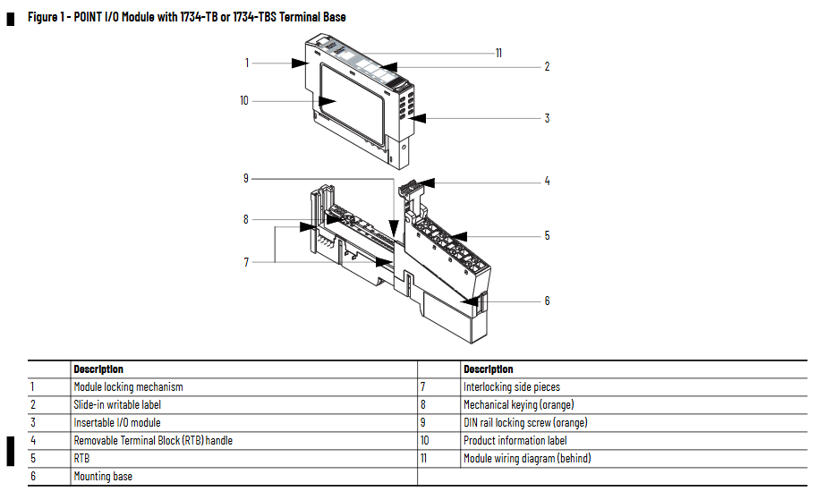
Applicable scenarios: In industrial automation control systems, it is used in conjunction with 1734 series POINT I/O modules (such as digital input/output modules, analog modules) to solve terminal expansion and power distribution problems in high-density wiring scenarios. It is compatible with 1734-TB/TBS (two-piece terminal base) and 1734-TOP/TOPS (one-piece terminal base), but not compatible with 1734-TB3/TB3S and 1734-TOP3/TOP3S bases.
Core content sorting
(1) Preparation in advance: Safety regulations and environmental requirements
Safety prerequisite
Operation qualification: Installation, wiring, and maintenance must be carried out by trained professionals and comply with local electrical regulations (such as NFPA 70E, EN/IEC standards).
Static electricity protection: The module is sensitive to static electricity. When operating, it is necessary to touch a grounded object to discharge and wear a grounding wristband. It is forbidden to touch the pins or components of the circuit board. When idle, it should be stored in anti-static packaging.
Attention to hazardous environments: If used in Class I, Zone 2 hazardous areas, it must be installed in a compliant enclosure and the wiring method must meet local explosion-proof standards; When replacing modules or terminals, power off or ensure that the environment is not hazardous.
Environmental and shell requirements
Environmental level: Suitable for industrial environments with pollution level 2, overvoltage category II (EN/IEC 60664-1), altitude up to 2000 meters (no need to downgrade), prohibited for residential environments.
Shell requirements: The module is of open design and needs to be installed inside a closed shell. The shell should have flame retardant properties (flame propagation level 5VA or non-metallic materials need to be certified), and the interior can only be accessed through tools. The protection level should refer to NEMA 250 or EN/IEC 60529 standards (such as dustproof and waterproof requirements).
Temperature range: Operating temperature -20 ° C~+55 ° C (-4 ° F~+131 ° F), non operating temperature -40 ° C~+85 ° C (-40 ° F~+185 ° F). Exceeding this range can cause module failure.
(2) Installation process: Base, module, and terminal block deployment
1. Install the terminal base (Mounting Base)
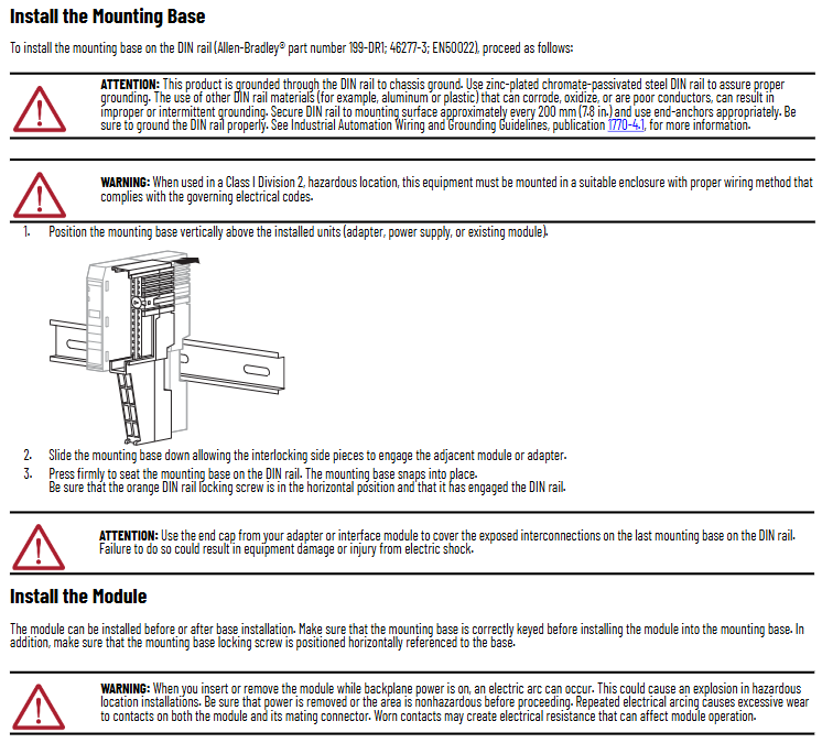
The module needs to be installed on a DIN rail through a 1734-TB/TBS or 1734-TOP/TOPS terminal base (recommended Allen Bradley 199-DR1 rail, compliant with EN 50022 standard). The steps are as follows:
Rail grounding confirmation: Use galvanized chromate passivated steel rails (aluminum/plastic rails are prone to oxidation or poor conductivity, which can cause grounding abnormalities), fix the rails every 200mm (7.8 inches), and install end anchors at both ends. Grounding must comply with the Industrial Automation Wiring and Grounding Guidelines (1770-4.1).
Positioning and installation of the base: Align the base vertically with the installed equipment (adapter, power supply, or existing module), slide down to engage the side interlocking structure with adjacent equipment, and press until the buckle is locked; Confirm that the orange DIN rail locking screw is in a horizontal position (unlocked) to prevent the base from loosening.
End cap protection: The end cap of the terminal base should be covered with an adapter or interface module to prevent electric shock or equipment damage to the exposed interconnected parts.
2. Install terminal module
The module can be deployed before or after installation on the base, and the key steps are as follows:
Base key switch configuration: Use a Phillips screwdriver to rotate the orange key switch on the base clockwise to align the corresponding module type number with the base groove (default position 1, refer to the module label for details), ensuring correct mechanical positioning.
Module installation: Insert the module vertically into the base and press it until the locking buckle is engaged; If the base is powered on, inserting/removing the module may generate an arc. In hazardous environments, power should be cut off first to avoid explosions caused by the arc.
3. Install Removable Terminal Block (RTB)
Module matching 1734-RTB (detachable terminal block), supports wire free replacement of base, installation steps:
Terminal block positioning: Insert the RTB handleless end (with arc-shaped buckle) into the base and rotate it to lock (hear a "click" sound).
Handle fixation: If the I/O module has been installed, fasten the RTB handle onto the module to ensure that the terminal block is stable; When disassembling, simply pull the handle upwards without removing the wiring.
Special terminal block operation:
1734-RTBS/RTB3S: Use a 3mm diameter screwdriver (1492-N90) to insert into the opening at a 73 ° angle and gently push up to lock/unlock the wiring.
1734-TOPS/TOP3S: Insert the screwdriver into the opening at a 97 ° angle to avoid damaging the terminals.
(3) Wiring guidance: Terminal definition and typical scenarios
The module needs to be used in conjunction with POINT I/O modules, and the wiring needs to be disconnected first. The key specifications are as follows:
1. Terminal definition
1734-CTM (Common Terminal Module): The terminals are divided into "Common 0-7", corresponding to the common end of the 8-channel I/O module (such as the power common line of the digital module), which centrally manages the common line and reduces wiring redundancy.
1734-VTM (Voltage Terminal Module): The terminals are divided into "Voltage out 0~7" (voltage output) and "Common 0~7" (common terminal), providing power distribution for on-site equipment. The output voltage needs to be matched with an external power source (10~28.8V DC or 120/240V AC).
2. Typical wiring scenarios
The document provides wiring diagrams for four core scenarios (Figures 4 to 7), with key examples as follows:
Leakage type input wiring (1734-IB8 module+CTM/VTM): The "signal terminal" of the 2-wire/3-wire proximity sensor is connected to the input terminal of the I/O module, the "power terminal" is connected to the "Voltage out" of the VTM, and the "common terminal" is connected to the "Common" of the CTM, achieving separate management of power and common terminals.
Source type output wiring (1734-OB8 module+CTM): The "positive pole" of the actuator (such as indicator lights, relays) is connected to the output terminal of the I/O module, and the "negative pole" is centrally connected to the "Common" of the CTM, simplifying multi device common terminal wiring.
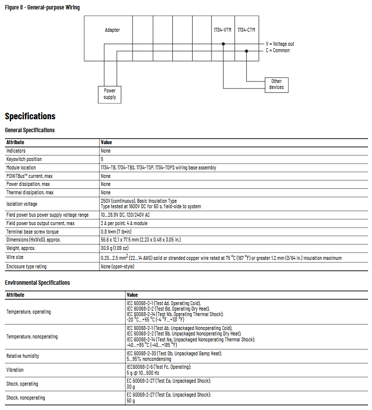
Universal wiring (adapter+CTM/VTM): VTM connects to an external power source to distribute voltage to other devices; CTM connects to the adapter's common end, achieving the aggregation of multiple module common lines and avoiding duplicate wiring.
3. Wiring parameters
Wire specifications: Supports solid or stranded copper wire of 0.25~2.5mm ² (22~14 AWG), with a maximum insulation thickness of 1.2mm (3/64 inches), and a rated temperature of ≥ 75 ° C (167 ° F).
Terminal torque: The tightening torque of the base screw is 0.8 N · m (7 lb · in), excessive tightening can damage the terminal.
(4) Technical parameters: Electrical and environmental specifications
1. General parameters
Parameter values
No indicator light
Key switch position 5
Adaptation base 1734-TB/TBS, 1734-TOP/TOPS
POINT Bus maximum current none
Maximum power consumption/heat dissipation none (only terminal expansion, no active components)
Isolation voltage 250V AC (continuous), 1600V DC (60 second test, on-site system side)
On site power bus voltage 10~28.8V DC, 120/240V AC
The maximum output current of the on-site power bus is 2A per point and 4A per module
The dimensions (height x width x depth) are approximately 56.6 x 12.1 x 77.5mm (2.23 x 0.48 x 3.05 inches)
Weight approximately 30.9g (1.09 ounces)
2. Environmental parameters
Parameter standards and numerical values
Working temperature -20 ° C~+55 ° C (-4 ° F~+131 ° F), in accordance with IEC 60068-2-1/2/14
Non working temperature -40 ° C~+85 ° C (-40 ° F~+185 ° F), in accordance with IEC 60068-2-1/2/14
Relative humidity of 5%~95% (non condensing), in accordance with IEC 60068-2-30
Vibration (working) 5g @ 10~500Hz, in accordance with IEC 60068-2-6
Impact (working) 30g, compliant with IEC 60068-2-27
50g impact (non working), in accordance with IEC 60068-2-27
3. Authentication information
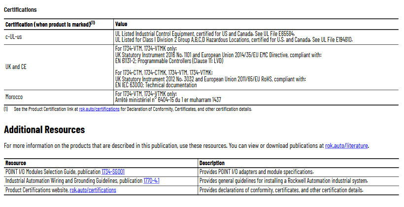
C-UL-US certification: UL listed industrial control equipment, suitable for the United States and Canada; Certification for Class I Zone 2 (Groups A/B/C/D) Hazardous Areas (UL Document E194810).
UK and CE certification: VTM/VTMK complies with UK Regulation 1101 of 2016 and EU EMC Directive 2014/35/EU (EN 61131-2); All modules comply with the EU 2011/65/EU RoHS Directive (EN IEC 63000).
Moroccan certification: VTM/VTMK complies with Moroccan Ministerial Decree No. 6404-15.
(5) Module dismantling and maintenance
Dismantling process: The module, adjacent module on the right side, and RTB (if wired) need to be dismantled first. The steps are:
Disconnect the RTB handle buckle and pull out the RTB;
Press the lock button on the top of the module and pull out the module;
Use a Phillips screwdriver to rotate the orange base locking screw to a vertical position, release the locking mechanism, and lift the base upwards to complete the removal.
Maintenance precautions: Do not disassemble the module by yourself in case of a malfunction and return it to the manufacturer for repair; When cleaning, only dry anti-static cloth can be used for wiping, and the use of cleaning agents is prohibited.
- OMRON
- ABB
- General Electric
- EMERSON
- Honeywell
- HIMA
- ALSTOM
- Rolls-Royce
- MOTOROLA
- Rockwell
- Siemens
- Woodward
- YOKOGAWA
- FOXBORO
- KOLLMORGEN
- MOOG
- KB
- YAMAHA
- BENDER
- TEKTRONIX
- Westinghouse
- AMAT
- AB
- XYCOM
- Yaskawa
- B&R
- Schneider
- KONGSBERG
- NI
- WATLOW
- ProSoft
- SEW
- ADVANCED
- Reliance
- TRICONEX
- METSO
- MAN
- Advantest
- STUDER
- DANAHER MOTION
- Bently
- Galil
- EATON
- MOLEX
- DEIF
- B&W
- ZYGO
- Aerotech
- DANFOSS
- Beijer
- Moxa
- Rexroth
- Johnson
- WAGO
- TOSHIBA
- BMCM
- SMC
- HITACHI
- HIRSCHMANN
- Application field
- XP POWER
- CTI
- TRICON
- STOBER
- Thinklogical
- Horner Automation
- Meggitt
- Fanuc
- Baldor
- SHINKAWA
- Other Brands
- UniOP
- KUKA
- Iba
- Beckhoff
-
 Basler D90 96801 100 PCB Card
 -
 Basler XR2002F Voltage Regulator (110 VAC, 48-480 Hz)
 -
 Basler SR8A-2B14B3A Regulator
 -
 Basler 9561500100 Module
 -
 Basler DECS-400 BE1-11 System
 -
 Basler DECS-100-B15 Excitation Control
 -
 Basler SCP 210 Frequency Controller
 -
 Basler SR4A-2B15B3A Static Voltage Regulator
 -
 Basler BE1-32R Power Relay
 -
 Basler PIA2400-17GM Power Interface Adapter
 -
 Basler MVC 232 Manual Voltage Control Module
 -
 Basler SSR 32-12 Static Voltage Regulator
 -
 Basler 5MW AVR Generator Voltage Regulator
 -
 Basler VR63-4B Voltage Regulator
 -
 Basler DECS-100-A05 AVR for Engine Generator
 -
 Basler DECS-100-B15 Automatic Voltage Regulator
 -
 Basler BE1-32R Directional Power Relay
 -
 Basler BE1-87B Differential Relay
 -
 Basler UFOV 260A Protective Module
 -
 Basler 9-2614-02-100 PCB Rev M
 -
Basler DECS-100-B15 Digital AVR
-
 Basler 9284900103 PS DECS-400N
 -
 Basler D4N3H1U Intertie Protection
 -
 Basler DECS-100-B15 A15 AVR
 -
 Basler KR4F Voltage Regulator
 -
 Basler BE26434 T14 Transformer
 -
 Basler SR8A-2B15B3A Regulator
 -
 Westinghouse 774B472A12 AR Relay
 -
Basler DECS-100-B15 AVR
-
Basler XR2002F Regulator 110V
-
Basler SR125-E Static Regulator
-
 Basler SSR 125-12 Regulator
 -
 Basler MOC2599 Motor Pot
 -
 Basler BE1-DFPR Feeder Relay
 -
 Basler CBS 305 Current Boost
 -
 Basler BE1-25 AutoSync
 -
 Basler MVC 300 Voltage Control
 -
 Basler BE3-25A AutoSync
 -
 Basler KR7FF Static Regulator
 -
 Basler 90-49000-100 Regulator
 -
 Basler 880 kVA Dry Type Transformer Specs
 -
 Basler Electric BE1-25 Sync-Check Relay Specs
 -
 Basler SSR 125-12 Voltage Regulator Specs
 -
 Basler Electric BE1-851 Overcurrent Relay Review
 -
Basler Electric 149D930G02 Control Sub-Assembly
-
 Basler Electric BE1-81O/UT Frequency Relay Specs
 -
 Basler Electric BE1-51/27C Overcurrent Relay
 -
 Basler Electric 149D956G02 Industrial Component
 -
Basler Electric BE1-51A Overcurrent Relay Specs
-
 Basler Electric BE1-40Q Loss of Excitation Relay
 -
 Basler DECS-200 Excitation Control System
 -
 Basler DECS-200 Voltage Regulator 56-277V AC / 125V DC
 -
Basler BE1-87T Transformer Differential Relay
-
 Basler RDP-110-S1 Protection Relay
 -
 Basler BE1-700V Digital Protective Relay
 -
 Basler BE1-951 Overcurrent Protection System
 -
 Basler DECS-300 Digital Excitation Control
 -
 Basler DECS-200 Digital Excitation Control
 -
 Basler DECS-200-1C Excitation Control System
 -
Basler DECS-200-1L Digital Excitation Control
-
 Basler Electric BE1-GPS Generator Protection System
 -
Basler Electric DECS-200-1C Digital Excitation Controller
-
 Basler Electric DECS125-15 Excitation Control with Power Module
 -
 Basler Electric BE1-87G Differential Relay
 -
 Basler Electric BE1-11 Protection System I5A3M2P2N0EA00
 -
Basler Electric DECS-200-1C Excitation Control System
-
Basler Electric BE1-11g Generator Protection Relay
-
Basler Electric DECS 125-15-B2C1 V2.0.9 Excitation Control
-
 Basler Electric BE1-81O/UT3ED1JA7N2F Frequency Relay
 -
Basler Electric BE1-81O/UT3EE1YB7N1F Frequency Relay
-
 Basler Electric DECS-200-1L Digital Excitation Control System
 -
Basler DECS125-15-B2C1 Excitation Control
-
 Basler 9507900205 SSR Retrofit Voltage Regulator
 -
 Basler BE2000E Digital Voltage Regulator
 -
 Basler BE1-GPS Generator Protection System
 -
Basler DECS-250-CN1CN1N Digital Excitation Control
-
 Basler DGC-2020 Genset Controller
 -
 Basler BE1-81O UT3ED1LA7N0F Frequency Relay (Variant)
 -
 Basler BE1-81O UT3EE1YA9S0F Frequency Relay (Variant)
 -
Basler BE1-81O Over/Under Frequency Relay
-
Basler DECS125-15 Digital Excitation Control
-
Basler Electric BE1-951 Overcurrent Protection System
-
 Basler Electric BE1-700V Digital Protective Relay
 -
 Basler Electric APR63-5 Automatic Voltage Regulator
 -
Basler Electric BE1-851 Overcurrent Protection System
-
Basler Electric DECS-250-LN1SN1N Excitation Control
-
 Basler Electric BE1-87T Transformer Differential Relay
 -
Basler Electric DECS-200-1L Excitation Control System
-
 Basler Electric 9310300100 DECS-300 Excitation Control
 -
 Basler Electric SSE-N 125-4.5KW Shunt Exciter Regulator
 -
 Basler Electric DGC-2020HD-5NS1DNSBA Genset Controller
 -
Basler Electric BE1-81-O/UT3EE1JB7N1F Frequency Relay
-
Basler Electric BE1-81T1EE1WA0N1F Frequency Relay
-
 Basler Electric BE1-25M1EA6PN5R1F Sync-Check Relay
 -
 Basler Electric BE1-GPS Generator Protection System
 -
Basler Electric DECS-250-LN1SN1N Excitation Control Rev V
-
 Basler Electric DECS-250-CN2CN1N Excitation Control
 -
Basler Electric BE1-50/51B-207 Overcurrent Relay
-
Basler Electric DECS-300-C0N0 Excitation Control System
-
Basler Electric DECS-200 Digital Excitation Control System
-
Basler Electric DECS-250-LN1CN1N Excitation Unit
-
Basler Electric DECS-250 LN2SA1D Excitation Unit Specs
-
Basler Electric BE1-87T Transformer Relay Review
-
Basler Electric BE1-11 Protection System
-
Basler Electric BE1-GPS100-E4N1H1N Protection System
-
 Allen-Bradley 442G-MABH-R Safety Module
 -
 Beckhoff CX1030-0111 PLC Assembly Profile
 -
 FANUC IC693CPU364 PLC Module
 -
 Orange Denmark Type 200816 220 PLC Specs
 -
 OMRON C200H-SNT31 Sysmac PLC Module
 -
 Allen Bradley 20AB022A3AYNANC0 PowerFlex 70
 -
 OMRON C200HW-PCU01 Position Control Unit
 -
 ABB AO845A-eA Analog Output Module
 -
 OMRON CJ1M-CPU22 CPU Unit
 -
 Allen Bradley 100-E265ED11 Contactor
 -
 Honeywell 51304511-100 Interface Module
 -
 SOLEXY BXF3S0101N0018 Gateway Module
 -
 OMRON CJ2H-CPU65 CPU Unit
 -
 Automation Direct GS2-45P0 AC Drive
 -
 M68-2000 2-Axis Motion CNC Controller
 -
 OMRON CJ1M-CPU11 V3.0 PLC CPU Unit
 -
 OMRON CJ1W-NC413 4-Axis Positioning Controller
 -
 OMRON 3G2A3-PRO16 Programming Console HMI
 -
 Siemens 3VT8440-2AA04-2GA2 Molded Case Circuit Breaker
 -
 Siemens 3RT5045 Contactor Series
 -
 OMRON C200HS-CPU01-E SYSMAC PLC Controller
 -
 OMRON C500-NC103-E Positioning Control Unit
 -
 OMRON CJ1W-TC001 Temperature Control Unit


