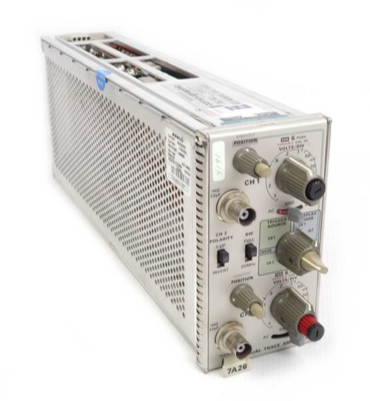
Foxboro I/A Series Compact 200 16 Slot Horizontal Substrate (31H2C480B4)
Module support: Provides 16 standard slots for installing Compact 200 series I/O modules (such as analog input/output modules, digital modules, HART communication modules, etc., as previously summarized for FBM218 module);
Signal and power distribution: The internal bus is used to achieve signal interaction between the substrate and various I/O modules, power supply, and communication connection between the modules and the higher-level controller;
Redundancy support: compatible with module level redundancy configurations (such as dual module redundancy), providing hardware foundation for high reliability of I/O subsystems;
Environmental adaptation: Adapt to harsh industrial environments such as dust, vibration, and wide temperature ranges to ensure stable operation of the I/O subsystem.
Foxboro I/A Series Compact 200 16 Slot Horizontal Substrate (31H2C480B4)
Core positioning and subsystem roles
The Compact 200 16 slot horizontal substrate is the "hardware backbone" of the Foxboro I/A Series Compact 200 I/O subsystem, with core functions including:
Module support: Provides 16 standard slots for installing Compact 200 series I/O modules (such as analog input/output modules, digital modules, HART communication modules, etc., as previously summarized for FBM218 module);
Signal and power distribution: The internal bus is used to achieve signal interaction between the substrate and various I/O modules, power supply, and communication connection between the modules and the higher-level controller;
Redundancy support: compatible with module level redundancy configurations (such as dual module redundancy), providing hardware foundation for high reliability of I/O subsystems;
Environmental adaptation: Adapt to harsh industrial environments such as dust, vibration, and wide temperature ranges to ensure stable operation of the I/O subsystem.
Structural design and installation characteristics
(1) Physical Structure and Dimensions
Exterior design: Adopting a horizontal layout, the overall structure is made of metal material frame (balancing strength and electromagnetic shielding), with slot markings (1-16) on the surface for easy module positioning and installation;
Key dimensions (refer to Compact 200 series standards):
Length: Approximately 483mm (19 inches, compatible with standard 19 inch cabinet installation);
Height: Approximately 130mm (5.12 inches);
Depth: Approximately 150mm (5.9 inches, including protruding connector);
Weight: Approximately 1.8kg (excluding modules), lightweight design facilitates cabinet assembly.
(2) Installation method and compatibility
Cabinet installation:
Support installation of 19 inch standard industrial cabinets, requiring a dedicated installation bracket (optional accessory), with a reserved installation depth of ≥ 200mm (including module insertion and removal space);
Compatible with "horizontal installation" (default), the installation angle can be adjusted through the adapter (please refer to the system installation guide);
DIN rail installation:
Supports installation with 35mm standard DIN rail (EN 60715 specification), which needs to be fixed with rail buckles, suitable for on-site scenarios without 19 inch cabinets (such as small control cabinets);
Module installation requirements:
Slot compatibility: All 16 slots support all I/O modules of the Compact 200 series, with no signal type restrictions (analog, digital, and communication modules can be mixed for installation);
Redundant module layout: If configuring redundant I/O modules (such as dual FBM218), they need to be installed in adjacent slots (such as slots 3 and 4, 5 and 6), and the first redundant module needs to be located in an odd numbered slot to ensure normal redundant communication and power switching functions.
Core functions and technical features
(1) Power distribution and redundancy support
Power input and distribution:
Supports dual 24V DC redundant power input (requires external redundant power module), with an allowable voltage fluctuation range of+5%/-10% (i.e. 21.6V DC -25.2V DC);
Internally integrated power distribution circuit, stably distributing redundant power to 16 slot I/O modules, with a maximum power supply current of ≥ 1A per module (meeting the power consumption requirements of most Compact 200 modules);
Power protection: Built in overcurrent protection (does not affect the power supply of other modules in case of single channel overcurrent), reverse connection protection (prevents the positive and negative poles of the power supply from reversing and damaging the substrate);
Redundant switching capability:
When the main power supply fails, the backup power supply can seamlessly switch within ≤ 10ms, ensuring that the I/O module has no power interruption and guaranteeing continuous acquisition/output of process signals;
Supporting "module level redundancy" power supply collaboration, redundant modules share the substrate power bus to avoid redundancy failure caused by single power supply failure.
(2) Signal bus and communication connection
Internal signal bus:
Integrate the "control signal bus" and "status monitoring bus": The control signal bus is used to transmit real-time data (such as 4-20mA analog and digital switch values) between the I/O module and the higher-level controller; The status monitoring bus is used to upload diagnostic information such as module faults and power status;
Bus speed: Control signal transmission rate ≥ 1Mbps, meeting the real-time requirements of industrial processes (delay ≤ 10ms);
Isolation design: Galvanic isolation (isolation voltage ≥ 500V AC/1 minute) is implemented between the signal bus and the power bus to prevent power interference from affecting signal transmission;
External communication interface:
A dedicated "controller connection port" (usually a multi pin industrial connector) is installed on the back of the substrate, which is connected to Foxboro I/A Series controllers (such as Evo controllers) through dedicated cables to achieve overall linkage between subsystems and control systems;
- ABB
- General Electric
- EMERSON
- Honeywell
- HIMA
- ALSTOM
- Rolls-Royce
- MOTOROLA
- Rockwell
- Siemens
- Woodward
- YOKOGAWA
- FOXBORO
- KOLLMORGEN
- MOOG
- KB
- YAMAHA
- BENDER
- TEKTRONIX
- Westinghouse
- AMAT
- AB
- XYCOM
- Yaskawa
- B&R
- Schneider
- Kongsberg
- NI
- WATLOW
- ProSoft
- SEW
- ADVANCED
- Reliance
- TRICONEX
- METSO
- MAN
- Advantest
- STUDER
- KONGSBERG
- DANAHER MOTION
- Bently
- Galil
- EATON
- MOLEX
- DEIF
- B&W
- ZYGO
- Aerotech
- DANFOSS
- Beijer
- Moxa
- Rexroth
- Johnson
- WAGO
- TOSHIBA
- BMCM
- SMC
- HITACHI
- HIRSCHMANN
- Application field
- XP POWER
- CTI
- TRICON
- STOBER
- Thinklogical
- Horner Automation
- Meggitt
- Fanuc
- Baldor
- SHINKAWA


