
Yokogawa 701944/701945 100:1 High Voltage Probe
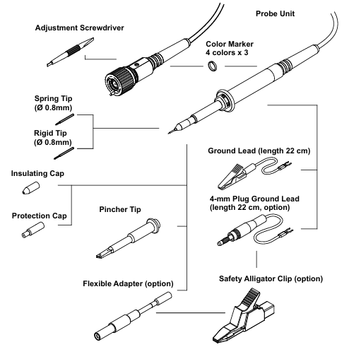
Replacement accessory set: Two sets are available, "Accessories Basic" (B9852HK) including 2 spring tips, 2 rigid tips, 2 clamp tips, and 2 grounding wires; The "Accessories HV" (B9852HL) includes one flexible adapter, one 4mm plug grounding wire, and two safety crocodile clips, making it easy to replace accessories in bulk after wear and tear.
Operation process
(1) Basic Connection
Connection between probe and oscilloscope: Connect the BNC connector of the probe to the 1M Ω input port of the oscilloscope, ensuring that the input impedance of the oscilloscope is set to 1M Ω; the probe ID pin will be automatically recognized by the oscilloscope, and the attenuation ratio will be automatically set to 10:1. If it is not automatically set, it needs to be manually adjusted to the corresponding gear to ensure accurate measurement data.
Grounding connection: Connect the probe grounding wire to the grounding potential, which can only be used for grounding connection and cannot be used for other purposes; It is strictly prohibited to use non designated grounding wires to prevent measurement errors or safety risks caused by poor grounding.
(2) Calibration process
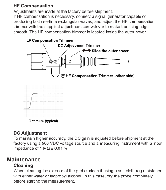
Low frequency compensation (LF Compensation): Connect the probe input to the probe compensation adjustment terminal (CAL/COMP terminal) of the oscilloscope, use the matching adjustment tool to rotate the low-frequency compensation micro adjuster, adjust the observed waveform to a standard square wave, ensure that the probe capacitance matches the oscilloscope input capacitance, and ensure measurement accuracy within the frequency range from DC to the upper limit of the bandwidth. Compensating for abnormalities (under compensation/over compensation) will cause waveform distortion and require readjustment.
HF Compensation: Calibration has been completed before leaving the factory. If adjustment is needed, a signal generator that can generate a fast rising edge rectangular wave needs to be connected. Slide the probe housing to expose the high-frequency compensation micro adjuster, and use an adjustment tool to smooth the rising edge to ensure the accuracy of high-frequency signal measurement.
DC Adjustment: Before leaving the factory, a measuring instrument with a 500VDC voltage source and a 1M Ω± 0.01% input impedance is used for calibration. Users do not need to make routine adjustments. If high-precision measurement is required, they can contact the dealer for professional calibration.
(3) Precautions for using the probe
Tip replacement: When replacing the contact tip, it is necessary to clamp the tip with pliers and pull it out vertically along the axis of the probe. It is strictly prohibited to clamp the white plastic insulator or housing (to avoid damaging the probe); When inserting the new tip, align it with the socket along the axis and gently press it until it fully fits, ensuring good contact.
Cable protection: To prevent the probe body from being impacted, excessive bending or pulling of the cable is not allowed to prevent damage or breakage of internal circuits, which may affect signal transmission.
Voltage derating: When the input signal frequency increases, the maximum input voltage of the probe will decrease. It is necessary to refer to the "Voltage derating curve" to select the appropriate input voltage to avoid overvoltage damage to the probe; Pulse measurement must comply with the corresponding limitations of peak pulse voltage, duty cycle, and duration to ensure safe use.
Maintenance and disposal
(1) Daily maintenance
Cleaning: When cleaning the probe housing, only a soft cloth dipped in water or isopropanol can be used to wipe it. After wiping, it must be completely dry before it can be used for measurement. Volatile chemicals such as benzene and diluents should not be used to prevent corrosion or deformation of the housing.
Accessory inspection: Regularly check whether the probe tip, grounding wire, and cable are intact. If the tip is worn, the cable is cracked, or the grounding wire is aged, the corresponding accessories should be replaced in a timely manner to avoid affecting measurement accuracy or causing safety hazards.
(2) Disposal of waste
When discarding probes or accessories, it is necessary to comply with the laws and regulations of the country/region where they are located and not to dispose of them at will; Components belonging to electronic waste, such as probe bodies and cables, must be disposed of in accordance with local electronic waste disposal regulations to avoid environmental pollution and comply with the EU WEEE Directive and relevant environmental requirements of each country.
Technical parameters
(1) Electrical parameters
Parameter 701944 701945 Remarks
Attenuation ratio 100:1 ± 2% (DC) 100:1 ± 2% (DC) requires the connection of an oscilloscope with an input impedance of 1M Ω± 1%
The typical value of voltage coefficient is 0.0005%/V, which reflects the influence of voltage changes on the attenuation ratio. The smaller the coefficient, the higher the accuracy
When the system bandwidth is -3dB, an oscilloscope with a bandwidth ≥ 500MHz needs to be connected to 400MHz and 250MHz, otherwise it is limited by the oscilloscope bandwidth
- OMRON
- ABB
- General Electric
- EMERSON
- Honeywell
- HIMA
- ALSTOM
- Rolls-Royce
- MOTOROLA
- Rockwell
- Siemens
- Woodward
- YOKOGAWA
- FOXBORO
- KOLLMORGEN
- MOOG
- KB
- YAMAHA
- BENDER
- TEKTRONIX
- Westinghouse
- AMAT
- AB
- XYCOM
- Yaskawa
- B&R
- Schneider
- KONGSBERG
- NI
- WATLOW
- ProSoft
- SEW
- ADVANCED
- Reliance
- TRICONEX
- METSO
- MAN
- Advantest
- STUDER
- DANAHER MOTION
- Bently
- Galil
- EATON
- MOLEX
- DEIF
- B&W
- ZYGO
- Aerotech
- DANFOSS
- Beijer
- Moxa
- Rexroth
- Johnson
- WAGO
- TOSHIBA
- BMCM
- SMC
- HITACHI
- HIRSCHMANN
- Application field
- XP POWER
- CTI
- TRICON
- STOBER
- Thinklogical
- Horner Automation
- Meggitt
- Fanuc
- Baldor
- SHINKAWA
- Other Brands
- UniOP
- KUKA
- Iba
- Beckhoff
-
 Mitsubishi MELSEC A2ASCPU PLC System
 -
 PC PMC25.2-002 PLC Module
 -
 B&R X20CP1382 Programmable Controller
 -
 Siemens C98043-A7002-L4 PC Board
 -
 Fanuc A16B-3300-0057 PCB Board
 -
 Schneider LV430403 Circuit Breaker TM160D
 -
 ABB CI810B 3BSE020520R1 PLC Interface
 -
 Omron R88D-HT10 Servo Drive
 -
 Omron CS1G-CPU43H CPU Unit
 -
 Mitsubishi QD70D4 Positioning Module
 -
 Siemens 6FC5110-0BB04-0AA1 Sinumerik 840C CPU
 -
 Siemens 3RT5045-1AC20 SIRIUS Contactor 75kW
 -
 Siemens 3VA2340-5HL32-0AA0 Circuit Breaker 400A
 -
 ABB HBS01-CJC I/O MTUS SD Series Module
 -
 Eberle MT42 Complete PLC Rack PLS514
 -
 Siemens C8451-A201-A9 PLC Card Slot Backplane
 -
 Cherokee ACX643 REV-B Power Supply Unit 100-240VAC
 -
 Schneider SSD1A320BDC1 Solid State Relay 20A
 -
 GE Fanuc IC694APU300 High Speed Counter Module
 -
 Schneider 140DA175300 Analog Output Module
 -
 Allen Bradley 1794-OA8I FLEX 8-Point Digital Output Module
 -
 Phoenix Contact PLC-BPT-24DC/1/SEN Solid State Relay Module
 -
 Schneider IG2000PG2 PLC Module Industrial Controller Card
 -
 Mitsubishi LE-40MTA-E Tension Controller Web Handling Control
 -
 Siemens 6FX1122-1AC02 PLC Card Industrial Interface Module
 -
 ABB AF210-30-11 Contactor Coil Voltage 110-240VAC
 -
 Mitsubishi GT2508-VTBD GT2508-VTBA HMI Touch Screen Panel
 -
 BPT 67200020 Touch Screen PLC Display Multifunction Terminal 50Hz
 -
 NORIS A1-91 PCB Rack Module A1-91-4 A1-91-5 A1-91-6 A1-91-7
 -
 Mitsubishi A1S61PN Power Supply Unit AnS Series 5VDC 5A
 -
 Pilz 312070AA PSSU H PLC1 FS SN SD Safety Module
 -
 Pasaban MTC-3044 PLC Rack with Power Supply Card
 -
 Schneider METSEPM8243 Power Meter PM800
 -
 Fanuc A16B-1212-0100-01 Power Supply Unit
 -
 Honeywell DPCB21010002 PCB IRTP-161 REV A
 -
 Siemens 6ES7315-2AH14-0AB0 CPU 315-2 DP
 -
 Omron GRT1-DA2V Analog Output Module 2 Channels
 -
 Mitsubishi FX3U-128MT/ESS PLC CPU Module
 -
 Schneider SSP05EMA12 Soft Starter Altistart 22
 -
 Mushroom 787602 Push Button Head 40mm
 -
 Hydraulik Elektronik EPM8900 91221 Proportional Module
 -
 ABB XZ C828 A101 Didt Dioder Snubber 3BHE039453R0101
 -
 ABB 3BHE032593R0001 Isolated Power Supply
 -
 ABB 3BHB02722R0001 single-phase charging transformer
 -
 ABB 3BHE006412R0101 UFC762AE101 main control board
 -
 ABB XVC770BE101 3BHE021083R0101 interface board
 -
 ABB 3BHE024747R0101 GD C801 Overvoltage Protection Motherboard
 -
 ABB 3BHE021887R0101 3BHB002751R0102 Variable Frequency Control Board
 -
 ABB SD812 power module 3BSC610023R0001
 -
 Automotive LC4A00010 Brushless Motor Controller
 -
 Doric NC500 Neuroscience Data Acquisition System
 -
 Honeywell X-DCS2000/EN Broadcast Manager
 -
 Kollmorgen S60600 servo drive 6A 480V
 -
 Honeywell 30751044-008 ROM Card
 -
 Honeywell 5SE1-12 Micro Switch Specifications
 -
 Schneider AS-BDAU-204 Analog Output Module
 -
 K93712 Expansion Kit Industrial Module
 -
 MGE DCHEN 3400116300 Circuit Board
 -
 Siemens 6SE7036-1EE85-1HA0 Rectifier Board
 -
 Renesas UPD70F3624GBA1 Microcontroller
 -
 Omron E5AC-CX4A5M-014 Temperature Controller Parameters
 -
 GE IS200TBCIH1BCE Contact Input Board
 -
 Fanuc A05B-2255-C101#EAW Teach Pendant Data
 -
Rieter RMC186C RMC RIO-1 PLC Controller
-
 Siemens PXC24.2-EF32.A Building Automation Controller
 -
 Fanuc A16B-1200-0220 PC Memory Board F3
 -
 Omron CJ2M-CPU33 PLC CPU Module
 -
 Beckhoff EL1918 Safety Input Terminal EtherCAT
 -
 Fanuc A16B-1212-0871 CNC PCB Board
 -
 GE Fanuc IC697BEM713J PLC Module
 -
 Mitsubishi A2ACPU-R21 PLC CPU Module
 -
 Programmable Relay 230V AC 16 Inputs 8 Outputs T2UK
 -
 Schneider F3SP71-4S Safety PLC Module
 -
 NEED-24DC- T2UK Programmable Relay 24V 16in 8out
 -
 Siemens 3RT1075-6SP36 SIRIUS Power Contactor 200kW
 -
 GE 1C31170G02 Printed Circuit Board Module 94V-0
 -
 BPT 67200020 Multifunction Touch Terminal 50Hz
 -
 Fanuc A16B-2200-0931 Option Board with Daughter Cards
 -
 Honeywell FC-SDOL-0424 I/O Module Board
 -
 Lenze EMF2179IB DeviceNet Communication Module
 -
 Yaskawa CIMR-JC4A0007BAA J1000 VFD 0.4kW
 -
 Yokogawa PSBCMNBN Bus Continuation Module ProSafe-PLC
 -
 Phoenix Contact PLC-BPT-24DC/1/SEN Solid-State Relay
 -
 Allen-Bradley 193-EC2AB E3 Plus Overload Relay
 -
 GE DS200TCTGG1AFF Turbine Control Board
 -
 Westinghouse 1C31170G02 Ovation Module
 -
 Mitsubishi A2ACPU21 Programmable Controller Review
 -
 710-95045-AD PLC I/O Operation Console Cable
 -
 Allen-Bradley 1785-L11B PLC-5 Processor Specifications
 -
 BEMAC UST-202-D 1307D V08B2 Circuit Board
 -
 Pilz 312070 PSSu H PLC1 FS Safety Module
 -
 Keyence QS-MB1 Safety Network Module Overview
 -
GE Fanuc IC693CPU372 CPU Module 90-30 Series
-
 Mitsubishi RJ71EIP91 EtherNet/IP Module
 -
 Schneider LXM62DD27D21000 Lexium 62 Servo Drive
 -
 Mitsubishi Q13UDEHCPU Universal PLC CPU Module
 -
 B&R X20CP3585 Programmable Controller X20 CPU
 -
 Siemens 6FC5203-0AF02-0AA0 Sinumerik Operator Panel
 -
 IWKA PG02 VKR TEL-Z Self-Sufficient Measuring System
 -
 Schneider BMXCPS2010 PLC Power Supply Modicon M340
 -
 Mitsubishi A171SCPU Motion Servo CPU Specifications
 -
 PLC Board with Finder 44.52 Relay Module 6A 250V
 -
 Honeywell DOP 09436601 Measurex Module Data
 -
 Fanuc A20B-8101-0320 CNC Circuit Board
 -
 KUAX 680I V.24 PLC Module 68142304
 -
 Allen Bradley 1785-L30B PLC 5/30 Processor
 -
 Phoenix ILC 191 ETH 2TX 2700976 Ethernet Controller
 -
 Siemens 6SY7000-0AC80 PLC Power Supply Module
 -
 Reliance Electric MACS 804.46.20 CWW PLC Drive
 -
 Omron CP1E-N60DR-D PLC CPU 36 Input 24 Output
 -
 Mitsubishi Melsec PLC System A2ACPU A63P AY13E AX82
 -
 Square D PAF361600DC1680 2000A Circuit Breaker
 -
 MERLIN GERIN STR 58U 5000A Electronic Trip Unit
 -
 Omron CJ1W-SCU21-V1 Serial Communication Unit
 -
 SICK S30A-6011EA S3000 Safety Laser Scanner
 -
 Mitsubishi Q00JCPU-S8 Universal Programmable Controller
 -
 Allen-Bradley 20AB9P6C3AYNANC0 PowerFlex 70 AC Drive
 -
 SYSMELEC Handheld Robot Automation Controller
 -
 LG Display LB315WRM-SVA1 32 Inch 4K LCD Panel
 -
 Mitsubishi Kakoki E Series PLC I/O Modules
 -
 Allen-Bradley 1440-VST02-01RA Dynamic Measurement Module
 -
 Beckhoff EL5042 EtherCAT Encoder Terminal
 -
 Beckhoff CX5010-0112 Embedded PC Controller
 -
 Guardmaster 440R-D22R2 Safety Relay Specifications
 -
 NL12880BC20-10ND Industrial Display Panel Data
 -
 LFI 12X5326-S1 Slide-in Control Board Technical Data
 -
 Modicon AS-9370-001 Programmable Controller Data
 -
 Mitsubishi Kakoki E-01B-4130 PLC Module Overview


