
Yokogawa AQ1000 OTDR Optical Time Domain Reflectometer
Internal memory: Approximately 480MB, non removable, used for storing files and system files (such as the ACKUP and USERS-MANUAL folders).
USB storage medium: Supports USB 1.0/1.1/2.0 standard USB devices (Type A ports), which can store waveform data, measurement conditions, etc; The Type B Micro-B port can connect the device as a high-capacity storage device to a computer and operate internal files.
6. System auxiliary functions
Power saving mode: can set screen brightness (4 levels, including off), distinguish between battery powered and USB-AC adapter powered brightness; Support automatic sleep mode. After the device is turned on and there is no operation for the set time (1/5/10/30 minutes), it will automatically enter sleep mode. If there is no operation for 2 hours, it will automatically shut down.
Language and Display Settings: Supports multi language switching, and can set the initial screen (TRACE/MAP/Setup Info.) and screen color (Color 1/Color 2/Black and White) for startup.
Firmware update: Store the new firmware on a USB storage medium and connect it to the Type A port to update the device firmware.
Operation process (core scenario)
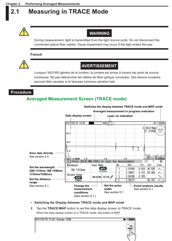
1. Average measurement (TRACE mode)
Mode switching: Click the TRACE/MAP button to ensure that the data is displayed in TRACE mode (the button displays as MAP).
Parameter settings: Click the Wavelength button to select the wavelength (1310nm/1550nm/1310nm+1550nm), set the distance range (automatic AUTO or manual, such as 200m-256km), and pulse width (automatic AUTO or manual, 3ns-20 μ s).
Start measurement: Press the AVG button, and the average measurement duration and laser on indicator will be displayed at the top of the screen. After the measurement is completed, it will automatically stop and perform event analysis, displaying waveforms and event results; Press the AVG button again to stop the measurement midway.
Data saving: Click on the floppy disk icon to save directly (in SOR/PDF/SOR+PDF format), or enable automatic saving in OTDR settings to automatically save data after measurement is completed.
2. Real time measurement (TRACE mode)
Parameter settings: Same as average measurement, select wavelength, distance range, pulse width (automatic or manual).
Start measurement: Press the REAL TIME button to activate the laser display and update the waveform in real-time; Press the REAL TIME button again to stop the measurement.
Data manipulation: During measurement, the cursor (displayed by clicking on the waveform position, dragging or clicking to move) and markers can be manipulated, and the current waveform data can also be saved (recording the waveform at the current time when saving).
3. Event analysis (TRACE mode)
Perform analysis: Press the MENU button and click the EVENT Analysis button. The device will automatically analyze the waveform and display the event (after averaging the measurements, it will be automatically executed without manual operation; when performing real-time measurements or loading real-time measurement SOR files, manual execution is required).
Result view: Information such as event number, distance, fusion loss, return loss, and event type is displayed in three forms: List, Separate, and All. You can click on the corresponding label to switch.
Event editing: Click on the waveform display area, the cursor will appear and the event editing interface will pop up. You can insert events (move the cursor to the target position and click the insert button), delete events (move the cursor to the event ▲ mark and click the delete button), and insert/delete distance reference point R.
4. Setting of qualified/unqualified judgment
Enter Settings: Press the MENU button, click OTDR Setup, and in the Setup Info. menu, click on the EVENT ANALYSIS area to enter the EVENT ANALYSIS SETUP screen.
Enable Judgment: Click the Pass Fail Judgment button and set it to ON.
Threshold setting: Set the threshold for each judgment item (such as connector loss ≤ 1.00dB, fusion loss ≤ 0.10dB, return loss ≥ 70dB, etc.).
View result: After the average measurement is completed, the unqualified events in the event list are highlighted in red, and the progress bar at the top of the TRACE mode displays the overall judgment result (green/red).
Data management
1. USB storage media operation
Connection and detection: Supports hot swapping, connects USB storage media (Type A port) when the device is turned on, and the device automatically detects it; When connecting, it is necessary to directly plug into the port without using a USB hub, and avoid frequent plugging and unplugging in a short period of time (with an interval of ≥ 10 seconds).
Data reading and writing precautions: When the USB storage medium access indicator light flashes or data is read or written, the medium cannot be removed or turned off, otherwise it may damage the medium or data; Only supports FAT format USB devices, does not support encrypted or protected USB devices.
2. Data saving and loading
Data saving: Press the MENU button, click the Save button, select the storage medium (internal memory/USB), file format (SOR/SOZ/SOR+JPG), set the file name, and save; Support automatic saving, enable Auto Save in OTDR settings, select the save mode (by date/custom User Define) and storage path.
- OMRON
- ABB
- General Electric
- EMERSON
- Honeywell
- HIMA
- ALSTOM
- Rolls-Royce
- MOTOROLA
- Rockwell
- Siemens
- Woodward
- YOKOGAWA
- FOXBORO
- KOLLMORGEN
- MOOG
- KB
- YAMAHA
- BENDER
- TEKTRONIX
- Westinghouse
- AMAT
- AB
- XYCOM
- Yaskawa
- B&R
- Schneider
- KONGSBERG
- NI
- WATLOW
- ProSoft
- SEW
- ADVANCED
- Reliance
- TRICONEX
- METSO
- MAN
- Advantest
- STUDER
- DANAHER MOTION
- Bently
- Galil
- EATON
- MOLEX
- DEIF
- B&W
- ZYGO
- Aerotech
- DANFOSS
- Beijer
- Moxa
- Rexroth
- Johnson
- WAGO
- TOSHIBA
- BMCM
- SMC
- HITACHI
- HIRSCHMANN
- Application field
- XP POWER
- CTI
- TRICON
- STOBER
- Thinklogical
- Horner Automation
- Meggitt
- Fanuc
- Baldor
- SHINKAWA
- Other Brands
- UniOP
- KUKA
- Iba
- Beckhoff
-
 Basler D90 96801 100 PCB Card
 -
 Basler XR2002F Voltage Regulator (110 VAC, 48-480 Hz)
 -
 Basler SR8A-2B14B3A Regulator
 -
 Basler 9561500100 Module
 -
 Basler DECS-400 BE1-11 System
 -
 Basler DECS-100-B15 Excitation Control
 -
 Basler SCP 210 Frequency Controller
 -
 Basler SR4A-2B15B3A Static Voltage Regulator
 -
 Basler BE1-32R Power Relay
 -
 Basler PIA2400-17GM Power Interface Adapter
 -
 Basler MVC 232 Manual Voltage Control Module
 -
 Basler SSR 32-12 Static Voltage Regulator
 -
 Basler 5MW AVR Generator Voltage Regulator
 -
 Basler VR63-4B Voltage Regulator
 -
 Basler DECS-100-A05 AVR for Engine Generator
 -
 Basler DECS-100-B15 Automatic Voltage Regulator
 -
 Basler BE1-32R Directional Power Relay
 -
 Basler BE1-87B Differential Relay
 -
 Basler UFOV 260A Protective Module
 -
 Basler 9-2614-02-100 PCB Rev M
 -
Basler DECS-100-B15 Digital AVR
-
 Basler 9284900103 PS DECS-400N
 -
 Basler D4N3H1U Intertie Protection
 -
 Basler DECS-100-B15 A15 AVR
 -
 Basler KR4F Voltage Regulator
 -
 Basler BE26434 T14 Transformer
 -
 Basler SR8A-2B15B3A Regulator
 -
 Westinghouse 774B472A12 AR Relay
 -
Basler DECS-100-B15 AVR
-
Basler XR2002F Regulator 110V
-
Basler SR125-E Static Regulator
-
 Basler SSR 125-12 Regulator
 -
 Basler MOC2599 Motor Pot
 -
 Basler BE1-DFPR Feeder Relay
 -
 Basler CBS 305 Current Boost
 -
 Basler BE1-25 AutoSync
 -
 Basler MVC 300 Voltage Control
 -
 Basler BE3-25A AutoSync
 -
 Basler KR7FF Static Regulator
 -
 Basler 90-49000-100 Regulator
 -
 Basler 880 kVA Dry Type Transformer Specs
 -
 Basler Electric BE1-25 Sync-Check Relay Specs
 -
 Basler SSR 125-12 Voltage Regulator Specs
 -
 Basler Electric BE1-851 Overcurrent Relay Review
 -
Basler Electric 149D930G02 Control Sub-Assembly
-
 Basler Electric BE1-81O/UT Frequency Relay Specs
 -
 Basler Electric BE1-51/27C Overcurrent Relay
 -
 Basler Electric 149D956G02 Industrial Component
 -
Basler Electric BE1-51A Overcurrent Relay Specs
-
 Basler Electric BE1-40Q Loss of Excitation Relay
 -
 Basler DECS-200 Excitation Control System
 -
 Basler DECS-200 Voltage Regulator 56-277V AC / 125V DC
 -
Basler BE1-87T Transformer Differential Relay
-
 Basler RDP-110-S1 Protection Relay
 -
 Basler BE1-700V Digital Protective Relay
 -
 Basler BE1-951 Overcurrent Protection System
 -
 Basler DECS-300 Digital Excitation Control
 -
 Basler DECS-200 Digital Excitation Control
 -
 Basler DECS-200-1C Excitation Control System
 -
Basler DECS-200-1L Digital Excitation Control
-
 Basler Electric BE1-GPS Generator Protection System
 -
Basler Electric DECS-200-1C Digital Excitation Controller
-
 Basler Electric DECS125-15 Excitation Control with Power Module
 -
 Basler Electric BE1-87G Differential Relay
 -
 Basler Electric BE1-11 Protection System I5A3M2P2N0EA00
 -
Basler Electric DECS-200-1C Excitation Control System
-
Basler Electric BE1-11g Generator Protection Relay
-
Basler Electric DECS 125-15-B2C1 V2.0.9 Excitation Control
-
 Basler Electric BE1-81O/UT3ED1JA7N2F Frequency Relay
 -
Basler Electric BE1-81O/UT3EE1YB7N1F Frequency Relay
-
 Basler Electric DECS-200-1L Digital Excitation Control System
 -
Basler DECS125-15-B2C1 Excitation Control
-
 Basler 9507900205 SSR Retrofit Voltage Regulator
 -
 Basler BE2000E Digital Voltage Regulator
 -
 Basler BE1-GPS Generator Protection System
 -
Basler DECS-250-CN1CN1N Digital Excitation Control
-
 Basler DGC-2020 Genset Controller
 -
 Basler BE1-81O UT3ED1LA7N0F Frequency Relay (Variant)
 -
 Basler BE1-81O UT3EE1YA9S0F Frequency Relay (Variant)
 -
Basler BE1-81O Over/Under Frequency Relay
-
Basler DECS125-15 Digital Excitation Control
-
Basler Electric BE1-951 Overcurrent Protection System
-
 Basler Electric BE1-700V Digital Protective Relay
 -
 Basler Electric APR63-5 Automatic Voltage Regulator
 -
Basler Electric BE1-851 Overcurrent Protection System
-
Basler Electric DECS-250-LN1SN1N Excitation Control
-
 Basler Electric BE1-87T Transformer Differential Relay
 -
Basler Electric DECS-200-1L Excitation Control System
-
 Basler Electric 9310300100 DECS-300 Excitation Control
 -
 Basler Electric SSE-N 125-4.5KW Shunt Exciter Regulator
 -
 Basler Electric DGC-2020HD-5NS1DNSBA Genset Controller
 -
Basler Electric BE1-81-O/UT3EE1JB7N1F Frequency Relay
-
Basler Electric BE1-81T1EE1WA0N1F Frequency Relay
-
 Basler Electric BE1-25M1EA6PN5R1F Sync-Check Relay
 -
 Basler Electric BE1-GPS Generator Protection System
 -
Basler Electric DECS-250-LN1SN1N Excitation Control Rev V
-
 Basler Electric DECS-250-CN2CN1N Excitation Control
 -
Basler Electric BE1-50/51B-207 Overcurrent Relay
-
Basler Electric DECS-300-C0N0 Excitation Control System
-
Basler Electric DECS-200 Digital Excitation Control System
-
Basler Electric DECS-250-LN1CN1N Excitation Unit
-
Basler Electric DECS-250 LN2SA1D Excitation Unit Specs
-
Basler Electric BE1-87T Transformer Relay Review
-
Basler Electric BE1-11 Protection System
-
Basler Electric BE1-GPS100-E4N1H1N Protection System
-
 Allen-Bradley 442G-MABH-R Safety Module
 -
 Beckhoff CX1030-0111 PLC Assembly Profile
 -
 FANUC IC693CPU364 PLC Module
 -
 Orange Denmark Type 200816 220 PLC Specs
 -
 OMRON C200H-SNT31 Sysmac PLC Module
 -
 Allen Bradley 20AB022A3AYNANC0 PowerFlex 70
 -
 OMRON C200HW-PCU01 Position Control Unit
 -
 ABB AO845A-eA Analog Output Module
 -
 OMRON CJ1M-CPU22 CPU Unit
 -
 Allen Bradley 100-E265ED11 Contactor
 -
 Honeywell 51304511-100 Interface Module
 -
 SOLEXY BXF3S0101N0018 Gateway Module
 -
 OMRON CJ2H-CPU65 CPU Unit
 -
 Automation Direct GS2-45P0 AC Drive
 -
 M68-2000 2-Axis Motion CNC Controller
 -
 OMRON CJ1M-CPU11 V3.0 PLC CPU Unit
 -
 OMRON CJ1W-NC413 4-Axis Positioning Controller
 -
 OMRON 3G2A3-PRO16 Programming Console HMI
 -
 Siemens 3VT8440-2AA04-2GA2 Molded Case Circuit Breaker
 -
 Siemens 3RT5045 Contactor Series
 -
 OMRON C200HS-CPU01-E SYSMAC PLC Controller
 -
 OMRON C500-NC103-E Positioning Control Unit
 -
 OMRON CJ1W-TC001 Temperature Control Unit


