
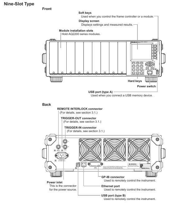
YOKOGAWA AQ2200 Series Multi Application Testing System
Optical sensor module: AQ2200-201/202 (interface module), AQ2200-231/232/241/242 (optical sensor head), AQ2200-211/212/215/221/222 (sensor module)
Other modules: attenuator (AQ2200-311/311A/312/331/332/342), optical switch (AQ2200-411/412/421), BERT (AQ2200-601), optical modulator (AQ2200-621/622), optical receiver (AQ2200-631), etc
Operation process guide
5.1 Module installation and uninstallation
Installation steps
If there is a blank panel in the slot, loosen the screw → slide down to remove the panel
Press the unlock button on the module panel and lift the locking lever
Align with the slot guide rail and slowly insert the module until it is fully seated
Slowly press the lever until you hear a "click" sound (2/3 slot module needs to tighten the bottom fixing screw)
Uninstalling steps
If it is a 2/3 slot module, first loosen the bottom fixing screw
Press the unlock button and gently lift the lever to unlock
Slowly pull out the module (protrude about 1cm, then pull it out by hand)
Hot swappable instructions: Modules can be installed/uninstalled while the frame controller is turned on. If a non SUMMAY/DETAIL screen is displayed during uninstallation, it will automatically switch to these two screens
5.2 Cable Connection
Fiber optic connection
Cleaning the fiber optic end face: Soak the cleaning paper in isopropanol, press and rotate the end face to wipe, then dry it with dry cleaning paper, and finally blow away residual dust with compressed air
Connection rule: The ANGLED PC ONLY interface is only connected to APC type fiber optic cables and is prohibited from connecting other types (to avoid damaging the plug)
Connector adapter: such as AQ9441 (for FP-LD module), AQ9335C (for sensor module), align the guide pin/hole connection according to the manual steps, and lock the lever
electrical connection
Coaxial cable: used for modules such as BERT and optical modulators. Before connecting, confirm that the signal output is turned off and tighten the connector with a torque of 0.9N-m
Power cord: Confirm that the instrument switch is turned off, connect it to a three pin grounded socket, and ensure that the voltage matches the rated value
Key module connection example (BER test)
BERT module (AQ2200-601) DATA OUT → Optical modulator (AQ2200-621/622) DATA IN
Light modulator LD IN → Light source module (AQ2200-111 PMF type) laser output
Optical modulator OPT OUT → DUT → Optical receiver (AQ2200-631) OPT IN
Optical receiver DATA OUT → BERT module DATA IN 1 (CDR)
5.3 Startup and Screen Operation
boot process
Confirm that the power connection is correct, press the POWER switch on the front panel of the frame controller
The instrument automatically performs self check, and after passing the test, it displays the SUMMAY screen (global module information) or Detail screen (individual module details)
Preheating requirement: To ensure measurement accuracy, it is recommended to preheat for at least 1 hour after turning on the machine
screen operation
SUMMAY screen: The blue background represents the "current module" (modifiable parameters), the light blue background represents the "current parameters", and the empty slot displays "NO MODULE"
Detail screen: The top displays the current module slot, allowing you to view/modify all parameters of the module (such as wavelength and attenuation values)
Hard key function (key buttons)
Hard key function keyboard mode corresponds to numbers
Switch to Detail Screen 7
SLOT ◄/► Switch current control module 8/9
Switch to SUMMAY screen 4
HOLD pauses screen updates, press again to resume 5
SYSTEM: Enter the system settings screen (date, password, etc.) 3
Maintenance and troubleshooting
6.1 Daily Maintenance
Cleaning requirements
Body: Wipe with a dry soft cloth after power failure. Do not use chemicals such as benzene or diluents (to avoid discoloration/deformation)
Optical interface: Clean with isopropanol and cleaning paper, and only use compressed air to remove dust from the sensitive surface of the sensor head (wiping is prohibited)
Electrical interface: Use compressed air to blow away dust, without using interface cover protective cap/terminal
Regularly replace parts
Suggested replacement cycle note for part name
Cooling fan for 40000 hours to ensure ventilation and avoid internal overheating
Lithium batteries will also be consumed even when the instrument is powered off for 3 years
ATTN module shutter 150000 times suitable for AQ2200-311/311A/312/331/332
LCD backlight for 30000 hours (default brightness 5) needs to be replaced when the brightness drops to half
Calibration requirements
Conventional module: It is recommended to calibrate once a year
AQ2200-111 (DFB-LD): Calibrate every 6 months due to semiconductor characteristics
Calibration method: Contact the Yokogawa dealer to adjust the parameters simultaneously
6.2 Troubleshooting
Common Problems and Solutions
Possible causes and solutions for the problem phenomenon
The instrument cannot be turned on. The power cord is not properly connected and the voltage does not match. Check the power cord connection and confirm that the voltage is between 90-264VAC
Laser lock without output, interlock plug not connected, unlock according to the process (password 1234)
PPG-ED cannot synchronize. The cable is not properly connected and the PPG and ED parameters do not match. Check the cable and confirm that the pattern and PRBS length of PPG and ED are consistent
OE displays LOS alarm for fiber not connected and low input power. Check the fiber connection and add an optical amplifier to increase power
- OMRON
- ABB
- General Electric
- EMERSON
- Honeywell
- HIMA
- ALSTOM
- Rolls-Royce
- MOTOROLA
- Rockwell
- Siemens
- Woodward
- YOKOGAWA
- FOXBORO
- KOLLMORGEN
- MOOG
- KB
- YAMAHA
- BENDER
- TEKTRONIX
- Westinghouse
- AMAT
- AB
- XYCOM
- Yaskawa
- B&R
- Schneider
- KONGSBERG
- NI
- WATLOW
- ProSoft
- SEW
- ADVANCED
- Reliance
- TRICONEX
- METSO
- MAN
- Advantest
- STUDER
- DANAHER MOTION
- Bently
- Galil
- EATON
- MOLEX
- DEIF
- B&W
- ZYGO
- Aerotech
- DANFOSS
- Beijer
- Moxa
- Rexroth
- Johnson
- WAGO
- TOSHIBA
- BMCM
- SMC
- HITACHI
- HIRSCHMANN
- Application field
- XP POWER
- CTI
- TRICON
- STOBER
- Thinklogical
- Horner Automation
- Meggitt
- Fanuc
- Baldor
- SHINKAWA
- Other Brands
- UniOP
- KUKA
- Iba
- Beckhoff
-
 Basler D90 96801 100 PCB Card
 -
 Basler XR2002F Voltage Regulator (110 VAC, 48-480 Hz)
 -
 Basler SR8A-2B14B3A Regulator
 -
 Basler 9561500100 Module
 -
 Basler DECS-400 BE1-11 System
 -
 Basler DECS-100-B15 Excitation Control
 -
 Basler SCP 210 Frequency Controller
 -
 Basler SR4A-2B15B3A Static Voltage Regulator
 -
 Basler BE1-32R Power Relay
 -
 Basler PIA2400-17GM Power Interface Adapter
 -
 Basler MVC 232 Manual Voltage Control Module
 -
 Basler SSR 32-12 Static Voltage Regulator
 -
 Basler 5MW AVR Generator Voltage Regulator
 -
 Basler VR63-4B Voltage Regulator
 -
 Basler DECS-100-A05 AVR for Engine Generator
 -
 Basler DECS-100-B15 Automatic Voltage Regulator
 -
 Basler BE1-32R Directional Power Relay
 -
 Basler BE1-87B Differential Relay
 -
 Basler UFOV 260A Protective Module
 -
 Basler 9-2614-02-100 PCB Rev M
 -
Basler DECS-100-B15 Digital AVR
-
 Basler 9284900103 PS DECS-400N
 -
 Basler D4N3H1U Intertie Protection
 -
 Basler DECS-100-B15 A15 AVR
 -
 Basler KR4F Voltage Regulator
 -
 Basler BE26434 T14 Transformer
 -
 Basler SR8A-2B15B3A Regulator
 -
 Westinghouse 774B472A12 AR Relay
 -
Basler DECS-100-B15 AVR
-
Basler XR2002F Regulator 110V
-
Basler SR125-E Static Regulator
-
 Basler SSR 125-12 Regulator
 -
 Basler MOC2599 Motor Pot
 -
 Basler BE1-DFPR Feeder Relay
 -
 Basler CBS 305 Current Boost
 -
 Basler BE1-25 AutoSync
 -
 Basler MVC 300 Voltage Control
 -
 Basler BE3-25A AutoSync
 -
 Basler KR7FF Static Regulator
 -
 Basler 90-49000-100 Regulator
 -
 Basler 880 kVA Dry Type Transformer Specs
 -
 Basler Electric BE1-25 Sync-Check Relay Specs
 -
 Basler SSR 125-12 Voltage Regulator Specs
 -
 Basler Electric BE1-851 Overcurrent Relay Review
 -
Basler Electric 149D930G02 Control Sub-Assembly
-
 Basler Electric BE1-81O/UT Frequency Relay Specs
 -
 Basler Electric BE1-51/27C Overcurrent Relay
 -
 Basler Electric 149D956G02 Industrial Component
 -
Basler Electric BE1-51A Overcurrent Relay Specs
-
 Basler Electric BE1-40Q Loss of Excitation Relay
 -
 Basler DECS-200 Excitation Control System
 -
 Basler DECS-200 Voltage Regulator 56-277V AC / 125V DC
 -
Basler BE1-87T Transformer Differential Relay
-
 Basler RDP-110-S1 Protection Relay
 -
 Basler BE1-700V Digital Protective Relay
 -
 Basler BE1-951 Overcurrent Protection System
 -
 Basler DECS-300 Digital Excitation Control
 -
 Basler DECS-200 Digital Excitation Control
 -
 Basler DECS-200-1C Excitation Control System
 -
Basler DECS-200-1L Digital Excitation Control
-
 Basler Electric BE1-GPS Generator Protection System
 -
Basler Electric DECS-200-1C Digital Excitation Controller
-
 Basler Electric DECS125-15 Excitation Control with Power Module
 -
 Basler Electric BE1-87G Differential Relay
 -
 Basler Electric BE1-11 Protection System I5A3M2P2N0EA00
 -
Basler Electric DECS-200-1C Excitation Control System
-
Basler Electric BE1-11g Generator Protection Relay
-
Basler Electric DECS 125-15-B2C1 V2.0.9 Excitation Control
-
 Basler Electric BE1-81O/UT3ED1JA7N2F Frequency Relay
 -
Basler Electric BE1-81O/UT3EE1YB7N1F Frequency Relay
-
 Basler Electric DECS-200-1L Digital Excitation Control System
 -
Basler DECS125-15-B2C1 Excitation Control
-
 Basler 9507900205 SSR Retrofit Voltage Regulator
 -
 Basler BE2000E Digital Voltage Regulator
 -
 Basler BE1-GPS Generator Protection System
 -
Basler DECS-250-CN1CN1N Digital Excitation Control
-
 Basler DGC-2020 Genset Controller
 -
 Basler BE1-81O UT3ED1LA7N0F Frequency Relay (Variant)
 -
 Basler BE1-81O UT3EE1YA9S0F Frequency Relay (Variant)
 -
Basler BE1-81O Over/Under Frequency Relay
-
Basler DECS125-15 Digital Excitation Control
-
Basler Electric BE1-951 Overcurrent Protection System
-
 Basler Electric BE1-700V Digital Protective Relay
 -
 Basler Electric APR63-5 Automatic Voltage Regulator
 -
Basler Electric BE1-851 Overcurrent Protection System
-
Basler Electric DECS-250-LN1SN1N Excitation Control
-
 Basler Electric BE1-87T Transformer Differential Relay
 -
Basler Electric DECS-200-1L Excitation Control System
-
 Basler Electric 9310300100 DECS-300 Excitation Control
 -
 Basler Electric SSE-N 125-4.5KW Shunt Exciter Regulator
 -
 Basler Electric DGC-2020HD-5NS1DNSBA Genset Controller
 -
Basler Electric BE1-81-O/UT3EE1JB7N1F Frequency Relay
-
Basler Electric BE1-81T1EE1WA0N1F Frequency Relay
-
 Basler Electric BE1-25M1EA6PN5R1F Sync-Check Relay
 -
 Basler Electric BE1-GPS Generator Protection System
 -
Basler Electric DECS-250-LN1SN1N Excitation Control Rev V
-
 Basler Electric DECS-250-CN2CN1N Excitation Control
 -
Basler Electric BE1-50/51B-207 Overcurrent Relay
-
Basler Electric DECS-300-C0N0 Excitation Control System
-
Basler Electric DECS-200 Digital Excitation Control System
-
Basler Electric DECS-250-LN1CN1N Excitation Unit
-
Basler Electric DECS-250 LN2SA1D Excitation Unit Specs
-
Basler Electric BE1-87T Transformer Relay Review
-
Basler Electric BE1-11 Protection System
-
Basler Electric BE1-GPS100-E4N1H1N Protection System
-
 Allen-Bradley 442G-MABH-R Safety Module
 -
 Beckhoff CX1030-0111 PLC Assembly Profile
 -
 FANUC IC693CPU364 PLC Module
 -
 Orange Denmark Type 200816 220 PLC Specs
 -
 OMRON C200H-SNT31 Sysmac PLC Module
 -
 Allen Bradley 20AB022A3AYNANC0 PowerFlex 70
 -
 OMRON C200HW-PCU01 Position Control Unit
 -
 ABB AO845A-eA Analog Output Module
 -
 OMRON CJ1M-CPU22 CPU Unit
 -
 Allen Bradley 100-E265ED11 Contactor
 -
 Honeywell 51304511-100 Interface Module
 -
 SOLEXY BXF3S0101N0018 Gateway Module
 -
 OMRON CJ2H-CPU65 CPU Unit
 -
 Automation Direct GS2-45P0 AC Drive
 -
 M68-2000 2-Axis Motion CNC Controller
 -
 OMRON CJ1M-CPU11 V3.0 PLC CPU Unit
 -
 OMRON CJ1W-NC413 4-Axis Positioning Controller
 -
 OMRON 3G2A3-PRO16 Programming Console HMI
 -
 Siemens 3VT8440-2AA04-2GA2 Molded Case Circuit Breaker
 -
 Siemens 3RT5045 Contactor Series
 -
 OMRON C200HS-CPU01-E SYSMAC PLC Controller
 -
 OMRON C500-NC103-E Positioning Control Unit
 -
 OMRON CJ1W-TC001 Temperature Control Unit


