YOKOGAWA AQ6150B/AQ6151B Optical Wavelength Meter
YOKOGAWA AQ6150B/AQ6151B Optical Wavelength Meter
Overview
The "Beginner's Guide" (6th Edition, document number IM AQ6150B-02EN) for YOKOGAWA AQ6150B/AQ6151B optical wavelength meters introduces the core functions of the two instruments (measuring light source optical characteristics, supporting single wavelength/multi wavelength detection), preparation before use (packaging content inspection, indoor installation requirements, power connection and power on/off process), basic operations (panel button/mouse/keyboard operation, parameter and string input), maintenance points (firmware updates, daily cleaning, component replacement cycles), and key specifications (wavelength range 900-1700nm, wavelength accuracy up to ± 0.2ppm, etc.), while emphasizing safety precautions (anti electric shock, anti laser eye injury). And provided user registration, technical support contact information, and access to relevant manuals.
Preparation before use
1. Packaging content inspection
After unboxing, it is necessary to confirm that the host, standard accessories, and optional accessories are complete. The standard accessories are as follows (optional accessories need to be purchased separately):
Category, Part Name, Model/Part Number, Quantity, Key Explanation
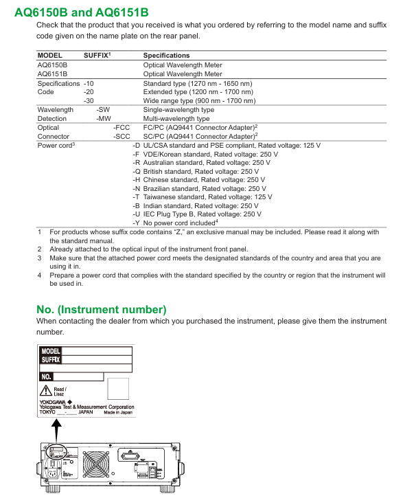
Host AQ6150B/AQ6151B Host -1 Confirm that the back nameplate model is consistent with the order, and record the instrument number (to be provided when contacting the dealer)
Standard Attachment - Power Supply Cord A1006WD (UL/CSA) 1 needs to be matched with regional standards, such as A1064WD for China and A1009WD for Europe; Suffix - Y without power cord
Standard attachment - Other rubber foot pads A9088ZM 2 sheets A9088ZM includes 2 foot pads for fixing instruments to prevent sliding
Standard attachments - Introduction to manuals, IM AQ6150B-02EN, etc. 1 copy each, including download request document, Chinese document, European Language Safety Manual, and global contact information list
Optional accessories - connector AQ9441 connector adapter (FC) AQ9441-FC - for optical input interface, also available in SC model (AQ9441-SC)
2. Instrument installation requirements
Installation environment: For indoor use only, avoid flammable and explosive environments, high vibration/high dust areas, direct sunlight or near heat sources
Placement requirements: Horizontal and stable tabletop, anti tilt; A ventilation gap of ≥ 20cm should be reserved between the bottom air inlet and the back air outlet to prevent internal overheating
Anti impact: When handling, turn off the power, disconnect all cables, and hold the handles on both sides with both hands to avoid falling (to prevent damage to the internal interferometer)
Rack installation: A separate rack kit (EIA standard 751535-E3, JIS standard 751535-J3) needs to be purchased, and the bottom should be supported and not obstruct the ventilation holes during installation
3. Power connection and power on/off
Power specifications: Rated voltage 100-240V AC, frequency 50/60Hz, maximum power consumption ≈ 100VA; allowable voltage range 90-264V AC, frequency 48-63Hz
Power on/off process:
Connect the power cord in the shutdown state (grounded, using a three pin socket);
Turn on the back MAIN POWER switch, and the front POWER light will turn orange;
After waiting for a few seconds, press the front POWER switch, the light turns green, and the instrument starts initialization (displaying STEP 1/6 to STEP 6/6);
To shut down, first press the front POWER switch, confirm the pop-up window, and then click "Yes". After the POWER light turns orange, turn off the MAIN POWER switch.

Basic Operations
1. Control method
Panel button operation:
Function area: including measurement control keys (REPEAT/SINGLE/STOP), function keys (PLAY/SEARCH/SETUP, etc.), and auxiliary keys (PRT SCN/LOCAL);
DATA ENTRY: Enter parameters using the numeric keypad, arrow keys, COARSE key, delete with BACK SPACE key, and confirm with ENTER key.
Mouse/keyboard operation:
Mouse: Left click=panel button operation, right-click to display function key list, can execute menu selection;
External keyboard: supports shortcut key mapping (such as [SHIFT]+[F1] to start display settings, [ALT]+[N] to switch COARSE/FINE mode), can input file names, labels, etc.
2. Core operating procedures
Parameter input:
Numerical input: Press the soft key with parameters, enter through the numeric keypad or arrow keys to adjust, confirm with the ENTER key (automatically reset to the nearest valid value if it exceeds the range);
String input: When entering a label/file name, a on-screen keyboard pops up, and characters can be selected using arrow keys. It supports cursor movement, insertion/deletion operations.
Fiber optic connection:
Clean the fiber end face: Use NTT-AT special cleaning agent, press and rotate to wipe (ensure no dust, avoid damaging the instrument optical interface);
Connecting the instrument: Connect the fiber optic cable to the "Optical INPUT" interface. If an attenuator/amplifier is required, it should be connected in series between the light source and the instrument, and the power offset (POWER OFFSET) should be set to match the actual power.
- ABB
- General Electric
- EMERSON
- Honeywell
- HIMA
- ALSTOM
- Rolls-Royce
- MOTOROLA
- Rockwell
- Siemens
- Woodward
- YOKOGAWA
- FOXBORO
- KOLLMORGEN
- MOOG
- KB
- YAMAHA
- BENDER
- TEKTRONIX
- Westinghouse
- AMAT
- AB
- XYCOM
- Yaskawa
- B&R
- Schneider
- Kongsberg
- NI
- WATLOW
- ProSoft
- SEW
- ADVANCED
- Reliance
- TRICONEX
- METSO
- MAN
- Advantest
- STUDER
- KONGSBERG
- DANAHER MOTION
- Bently
- Galil
- EATON
- MOLEX
- DEIF
- B&W
- ZYGO
- Aerotech
- DANFOSS
- Beijer
- Moxa
- Rexroth
- Johnson
- WAGO
- TOSHIBA
- BMCM
- SMC
- HITACHI
- HIRSCHMANN
- Application field
- XP POWER
- CTI
- TRICON
- STOBER
- Thinklogical
- Horner Automation
- Meggitt
- Fanuc
- Baldor
- SHINKAWA
- Other Brands


