
YOKOGAWA AQ6150B/AQ6151B Optical Wavelength Meter
YOKOGAWA AQ6150B/AQ6151B Optical Wavelength Meter
Overview
The "Beginner's Guide" (6th Edition, document number IM AQ6150B-02EN) for YOKOGAWA AQ6150B/AQ6151B optical wavelength meters introduces the core functions of the two instruments (measuring light source optical characteristics, supporting single wavelength/multi wavelength detection), preparation before use (packaging content inspection, indoor installation requirements, power connection and power on/off process), basic operations (panel button/mouse/keyboard operation, parameter and string input), maintenance points (firmware updates, daily cleaning, component replacement cycles), and key specifications (wavelength range 900-1700nm, wavelength accuracy up to ± 0.2ppm, etc.), while emphasizing safety precautions (anti electric shock, anti laser eye injury). And provided user registration, technical support contact information, and access to relevant manuals.
Preparation before use
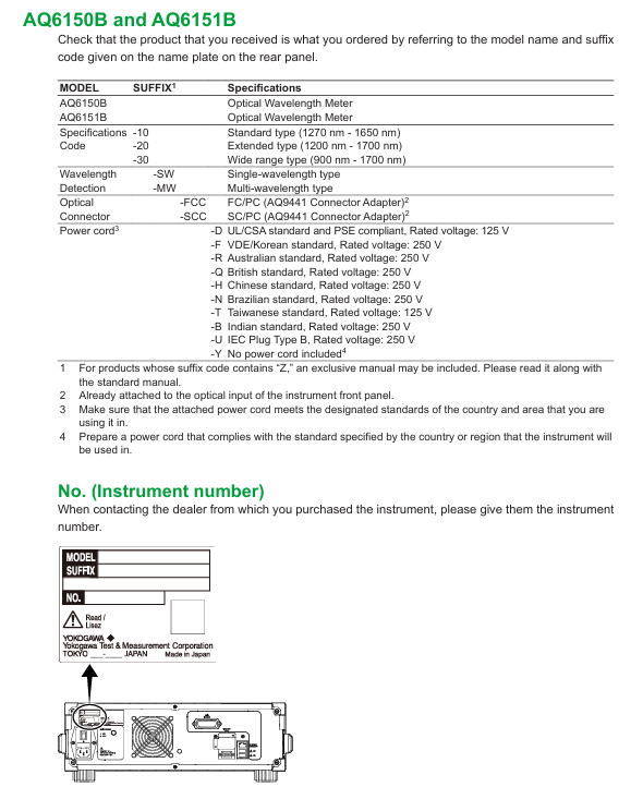
1. Packaging content inspection
After unboxing, it is necessary to confirm that the host, standard accessories, and optional accessories are complete. The standard accessories are as follows (optional accessories need to be purchased separately):
Category, Part Name, Model/Part Number, Quantity, Key Explanation
Host AQ6150B/AQ6151B Host -1 Confirm that the back nameplate model is consistent with the order, and record the instrument number (to be provided when contacting the dealer)
Standard Attachment - Power Supply Cord A1006WD (UL/CSA) 1 needs to be matched with regional standards, such as A1064WD for China and A1009WD for Europe; Suffix - Y without power cord
Standard attachment - Other rubber foot pads A9088ZM 2 sheets A9088ZM includes 2 foot pads for fixing instruments to prevent sliding
Standard attachments - Introduction to manuals, IM AQ6150B-02EN, etc. 1 copy each, including download request document, Chinese document, European Language Safety Manual, and global contact information list
Optional accessories - connector AQ9441 connector adapter (FC) AQ9441-FC - for optical input interface, also available in SC model (AQ9441-SC)
2. Instrument installation requirements
Installation environment: For indoor use only, avoid flammable and explosive environments, high vibration/high dust areas, direct sunlight or near heat sources
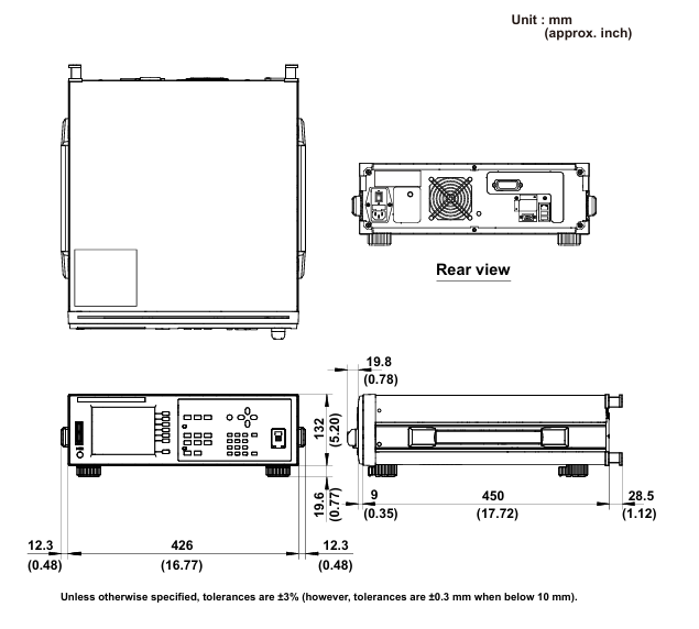
Placement requirements: Horizontal and stable tabletop, anti tilt; A ventilation gap of ≥ 20cm should be reserved between the bottom air inlet and the back air outlet to prevent internal overheating
Anti impact: When handling, turn off the power, disconnect all cables, and hold the handles on both sides with both hands to avoid falling (to prevent damage to the internal interferometer)
Rack installation: A separate rack kit (EIA standard 751535-E3, JIS standard 751535-J3) needs to be purchased, and the bottom should be supported and not obstruct the ventilation holes during installation
3. Power connection and power on/off
Power specifications: Rated voltage 100-240V AC, frequency 50/60Hz, maximum power consumption ≈ 100VA; allowable voltage range 90-264V AC, frequency 48-63Hz
Power on/off process:
Connect the power cord in the shutdown state (grounded, using a three pin socket);
Turn on the back MAIN POWER switch, and the front POWER light will turn orange;
After waiting for a few seconds, press the front POWER switch, the light turns green, and the instrument starts initialization (displaying STEP 1/6 to STEP 6/6);
To shut down, first press the front POWER switch, confirm the pop-up window, and then click "Yes". After the POWER light turns orange, turn off the MAIN POWER switch.
Basic Operations
1. Control method
Panel button operation:
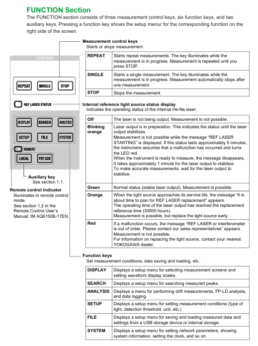
Function area: including measurement control keys (REPEAT/SINGLE/STOP), function keys (PLAY/SEARCH/SETUP, etc.), and auxiliary keys (PRT SCN/LOCAL);
DATA ENTRY: Enter parameters using the numeric keypad, arrow keys, COARSE key, delete with BACK SPACE key, and confirm with ENTER key.
Mouse/keyboard operation:
Mouse: Left click=panel button operation, right-click to display function key list, can execute menu selection;
External keyboard: supports shortcut key mapping (such as [SHIFT]+[F1] to start display settings, [ALT]+[N] to switch COARSE/FINE mode), can input file names, labels, etc.
2. Core operating procedures
Parameter input:
Numerical input: Press the soft key with parameters, enter through the numeric keypad or arrow keys to adjust, confirm with the ENTER key (automatically reset to the nearest valid value if it exceeds the range);
String input: When entering a label/file name, a on-screen keyboard pops up, and characters can be selected using arrow keys. It supports cursor movement, insertion/deletion operations.
Fiber optic connection:
Clean the fiber end face: Use NTT-AT special cleaning agent, press and rotate to wipe (ensure no dust, avoid damaging the instrument optical interface);
Connecting the instrument: Connect the fiber optic cable to the "Optical INPUT" interface. If an attenuator/amplifier is required, it should be connected in series between the light source and the instrument, and the power offset (POWER OFFSET) should be set to match the actual power.
Maintenance and Calibration
1. Firmware update
Update purpose: To enhance the functionality and usability of the instrument, the latest firmware (. UPD format) needs to be downloaded from the Yokogawa official website;
Update method:
USB update: Create an "Update" folder in the USB root directory, place the firmware file, and execute it through System → System Information → Update (USB);
Network update: Connect to the PC via Ethernet, copy the firmware to the internal Update directory of the instrument, and execute it through Update (NETWORK);
Attention: Do not turn off the power during the update. The instrument will automatically restart after the update, and the settings data will be initialized (backup is required in advance).
2. Daily maintenance
External cleaning: After power off, wipe the body and operation panel with a dry cloth, and prohibit chemicals such as benzene and diluents (to avoid discoloration and deformation);
Optical interface cleaning:
Connector adapter: Insert a rod-shaped cleaning agent into the optical interface and rotate it for cleaning;
Fiber end face: After power off, remove the adapter and wipe the plug end face with an alcohol swab (use a new swab each time).
3. Component replacement cycle
Key Explanation of Component Name Replacement Cycle/Service Life
LCD backlight ≈ 50000 hours (normal use) may experience brightness degradation after reaching its lifespan, and dealers need to be contacted for replacement
Internal reference light source (He Ne laser) ≈ 40000 hours (recommended to replace 30000 hours). When the lifespan is approaching, the REF Laser STATION LED turns orange, and when it malfunctions, it turns red (needs to be replaced immediately)
Optical input internal plug ≈ 2 years (normal use) Frequent plugging and unplugging may cause wear and affect measurement accuracy
The cooling fan should be replaced regularly every 7 years to prevent the instrument from overheating
Backup battery (lithium battery) for 7 years to store settings data, to be replaced promptly upon expiration
Safety and Compliance
1. Safety Warning
Warning (risk of fatal/serious injury):
Laser or instrument optical input interfaces that cannot be directly measured (may cause blindness);
Grounding must be used, and ungrounded extension cords are prohibited;
Do not use in flammable and explosive environments, and do not disassemble the instrument by yourself (there is high pressure inside).
CAUTION (Minor Injury/Equipment Damage Risk):
The instrument is a Class A industrial equipment, which may cause radio interference when used in residential areas and needs to be resolved by the user themselves;
Avoid strong light with an input power of ≥+18dBm (which may damage internal optical components), and connect the light source after the instrument is started.
2. Compliance requirements
Environmental compliance: Complies with the EU WEEE Directive (must not be mixed with household waste for disposal) and the Battery Directive (lithium batteries must be recycled separately);
Laser compliance: The built-in laser light source is Class 1 (compliant with IEC 60825-1:2014), with a maximum laser power of 5mW for AQ6150B and 15mW for AQ6151B, both with a wavelength of 633nm;
Regional compliance: Taiwan region needs to check the restricted substance information of power cord (A1100WD) (designated link on the official website).
Key specification parameters
The core specifications of AQ6150B/AQ6151B are as follows (specific to model and suffix):
Specification category specific parameters
Applicable to fiber optic SM (ITU-T G.652)
Wavelength range standard type 1270-1650nm, extended type 1200-1700nm, wide range type 900-1700nm
The wavelength accuracy of AQ6150B is up to ± 0.7ppm, and AQ6151B is up to ± 0.2ppm (1550nm, normal update rate)
Minimum power range -40dBm (1200-1600nm), maximum+10dBm, safe input power+18dBm
Power accuracy ± 0.5dB (1550nm, -10dBm)
Measurement time normal update rate ≤ 0.3s, fast update rate ≤ 0.2s
Display device 5.7-inch color LCD (resolution 640 × 480 pixels)
Interface GP-IB, Ethernet, USB (2 in front and 2 in back), VGA output
The working environment temperature is 5-35 ℃, and the humidity is 20-85% RH (without condensation); Performance guarantee temperature 10-30 ℃
- OMRON
- ABB
- General Electric
- EMERSON
- Honeywell
- HIMA
- ALSTOM
- Rolls-Royce
- MOTOROLA
- Rockwell
- Siemens
- Woodward
- YOKOGAWA
- FOXBORO
- KOLLMORGEN
- MOOG
- KB
- YAMAHA
- BENDER
- TEKTRONIX
- Westinghouse
- AMAT
- AB
- XYCOM
- Yaskawa
- B&R
- Schneider
- KONGSBERG
- NI
- WATLOW
- ProSoft
- SEW
- ADVANCED
- Reliance
- TRICONEX
- METSO
- MAN
- Advantest
- STUDER
- DANAHER MOTION
- Bently
- Galil
- EATON
- MOLEX
- DEIF
- B&W
- ZYGO
- Aerotech
- DANFOSS
- Beijer
- Moxa
- Rexroth
- Johnson
- WAGO
- TOSHIBA
- BMCM
- SMC
- HITACHI
- HIRSCHMANN
- Application field
- XP POWER
- CTI
- TRICON
- STOBER
- Thinklogical
- Horner Automation
- Meggitt
- Fanuc
- Baldor
- SHINKAWA
- Other Brands
- UniOP
- KUKA
- Iba
- Beckhoff
-
 Basler D90 96801 100 PCB Card
 -
 Basler XR2002F Voltage Regulator (110 VAC, 48-480 Hz)
 -
 Basler SR8A-2B14B3A Regulator
 -
 Basler 9561500100 Module
 -
 Basler DECS-400 BE1-11 System
 -
 Basler DECS-100-B15 Excitation Control
 -
 Basler SCP 210 Frequency Controller
 -
 Basler SR4A-2B15B3A Static Voltage Regulator
 -
 Basler BE1-32R Power Relay
 -
 Basler PIA2400-17GM Power Interface Adapter
 -
 Basler MVC 232 Manual Voltage Control Module
 -
 Basler SSR 32-12 Static Voltage Regulator
 -
 Basler 5MW AVR Generator Voltage Regulator
 -
 Basler VR63-4B Voltage Regulator
 -
 Basler DECS-100-A05 AVR for Engine Generator
 -
 Basler DECS-100-B15 Automatic Voltage Regulator
 -
 Basler BE1-32R Directional Power Relay
 -
 Basler BE1-87B Differential Relay
 -
 Basler UFOV 260A Protective Module
 -
 Basler 9-2614-02-100 PCB Rev M
 -
Basler DECS-100-B15 Digital AVR
-
 Basler 9284900103 PS DECS-400N
 -
 Basler D4N3H1U Intertie Protection
 -
 Basler DECS-100-B15 A15 AVR
 -
 Basler KR4F Voltage Regulator
 -
 Basler BE26434 T14 Transformer
 -
 Basler SR8A-2B15B3A Regulator
 -
 Westinghouse 774B472A12 AR Relay
 -
Basler DECS-100-B15 AVR
-
Basler XR2002F Regulator 110V
-
Basler SR125-E Static Regulator
-
 Basler SSR 125-12 Regulator
 -
 Basler MOC2599 Motor Pot
 -
 Basler BE1-DFPR Feeder Relay
 -
 Basler CBS 305 Current Boost
 -
 Basler BE1-25 AutoSync
 -
 Basler MVC 300 Voltage Control
 -
 Basler BE3-25A AutoSync
 -
 Basler KR7FF Static Regulator
 -
 Basler 90-49000-100 Regulator
 -
 Basler 880 kVA Dry Type Transformer Specs
 -
 Basler Electric BE1-25 Sync-Check Relay Specs
 -
 Basler SSR 125-12 Voltage Regulator Specs
 -
 Basler Electric BE1-851 Overcurrent Relay Review
 -
Basler Electric 149D930G02 Control Sub-Assembly
-
 Basler Electric BE1-81O/UT Frequency Relay Specs
 -
 Basler Electric BE1-51/27C Overcurrent Relay
 -
 Basler Electric 149D956G02 Industrial Component
 -
Basler Electric BE1-51A Overcurrent Relay Specs
-
 Basler Electric BE1-40Q Loss of Excitation Relay
 -
 Basler DECS-200 Excitation Control System
 -
 Basler DECS-200 Voltage Regulator 56-277V AC / 125V DC
 -
Basler BE1-87T Transformer Differential Relay
-
 Basler RDP-110-S1 Protection Relay
 -
 Basler BE1-700V Digital Protective Relay
 -
 Basler BE1-951 Overcurrent Protection System
 -
 Basler DECS-300 Digital Excitation Control
 -
 Basler DECS-200 Digital Excitation Control
 -
 Basler DECS-200-1C Excitation Control System
 -
Basler DECS-200-1L Digital Excitation Control
-
 Basler Electric BE1-GPS Generator Protection System
 -
Basler Electric DECS-200-1C Digital Excitation Controller
-
 Basler Electric DECS125-15 Excitation Control with Power Module
 -
 Basler Electric BE1-87G Differential Relay
 -
 Basler Electric BE1-11 Protection System I5A3M2P2N0EA00
 -
Basler Electric DECS-200-1C Excitation Control System
-
Basler Electric BE1-11g Generator Protection Relay
-
Basler Electric DECS 125-15-B2C1 V2.0.9 Excitation Control
-
 Basler Electric BE1-81O/UT3ED1JA7N2F Frequency Relay
 -
Basler Electric BE1-81O/UT3EE1YB7N1F Frequency Relay
-
 Basler Electric DECS-200-1L Digital Excitation Control System
 -
Basler DECS125-15-B2C1 Excitation Control
-
 Basler 9507900205 SSR Retrofit Voltage Regulator
 -
 Basler BE2000E Digital Voltage Regulator
 -
 Basler BE1-GPS Generator Protection System
 -
Basler DECS-250-CN1CN1N Digital Excitation Control
-
 Basler DGC-2020 Genset Controller
 -
 Basler BE1-81O UT3ED1LA7N0F Frequency Relay (Variant)
 -
 Basler BE1-81O UT3EE1YA9S0F Frequency Relay (Variant)
 -
Basler BE1-81O Over/Under Frequency Relay
-
Basler DECS125-15 Digital Excitation Control
-
Basler Electric BE1-951 Overcurrent Protection System
-
 Basler Electric BE1-700V Digital Protective Relay
 -
 Basler Electric APR63-5 Automatic Voltage Regulator
 -
Basler Electric BE1-851 Overcurrent Protection System
-
Basler Electric DECS-250-LN1SN1N Excitation Control
-
 Basler Electric BE1-87T Transformer Differential Relay
 -
Basler Electric DECS-200-1L Excitation Control System
-
 Basler Electric 9310300100 DECS-300 Excitation Control
 -
 Basler Electric SSE-N 125-4.5KW Shunt Exciter Regulator
 -
 Basler Electric DGC-2020HD-5NS1DNSBA Genset Controller
 -
Basler Electric BE1-81-O/UT3EE1JB7N1F Frequency Relay
-
Basler Electric BE1-81T1EE1WA0N1F Frequency Relay
-
 Basler Electric BE1-25M1EA6PN5R1F Sync-Check Relay
 -
 Basler Electric BE1-GPS Generator Protection System
 -
Basler Electric DECS-250-LN1SN1N Excitation Control Rev V
-
 Basler Electric DECS-250-CN2CN1N Excitation Control
 -
Basler Electric BE1-50/51B-207 Overcurrent Relay
-
Basler Electric DECS-300-C0N0 Excitation Control System
-
Basler Electric DECS-200 Digital Excitation Control System
-
Basler Electric DECS-250-LN1CN1N Excitation Unit
-
Basler Electric DECS-250 LN2SA1D Excitation Unit Specs
-
Basler Electric BE1-87T Transformer Relay Review
-
Basler Electric BE1-11 Protection System
-
Basler Electric BE1-GPS100-E4N1H1N Protection System
-
 Allen-Bradley 442G-MABH-R Safety Module
 -
 Beckhoff CX1030-0111 PLC Assembly Profile
 -
 FANUC IC693CPU364 PLC Module
 -
 Orange Denmark Type 200816 220 PLC Specs
 -
 OMRON C200H-SNT31 Sysmac PLC Module
 -
 Allen Bradley 20AB022A3AYNANC0 PowerFlex 70
 -
 OMRON C200HW-PCU01 Position Control Unit
 -
 ABB AO845A-eA Analog Output Module
 -
 OMRON CJ1M-CPU22 CPU Unit
 -
 Allen Bradley 100-E265ED11 Contactor
 -
 Honeywell 51304511-100 Interface Module
 -
 SOLEXY BXF3S0101N0018 Gateway Module
 -
 OMRON CJ2H-CPU65 CPU Unit
 -
 Automation Direct GS2-45P0 AC Drive
 -
 M68-2000 2-Axis Motion CNC Controller
 -
 OMRON CJ1M-CPU11 V3.0 PLC CPU Unit
 -
 OMRON CJ1W-NC413 4-Axis Positioning Controller
 -
 OMRON 3G2A3-PRO16 Programming Console HMI
 -
 Siemens 3VT8440-2AA04-2GA2 Molded Case Circuit Breaker
 -
 Siemens 3RT5045 Contactor Series
 -
 OMRON C200HS-CPU01-E SYSMAC PLC Controller
 -
 OMRON C500-NC103-E Positioning Control Unit
 -
 OMRON CJ1W-TC001 Temperature Control Unit


