
Konica Minolta CM-3700A-U Plus spectrophotometer
(1) Equipment Introduction
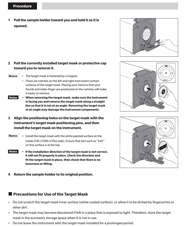
CM-3700A-U Plus is a reflective high-precision fixed spectrophotometer developed specifically for measuring color and color difference in various industrial fields, meeting the high-precision requirements for color quality control in industrial production.
(2) Packaging and Protection
It is necessary to properly store all packaging materials (cardboard boxes, cushioning materials, plastic bags, etc.) used during equipment transportation. As the equipment is a precision measuring instrument, these materials are needed to reduce vibration and impact during subsequent maintenance and transportation; If the packaging materials are lost or damaged, please contact an authorized service agency.
When the equipment leaves the factory, the target mask is not installed at the target mask installation location, but a protective cover is installed to protect the sample measurement component (integrating ball opening). Before use, the protective cover must be removed, and during transportation, the protective cover must be installed. At the same time, the protective cover that comes with the equipment should be stored and used properly.
Attachment information
(1) Standard attachments
Attachment Name, Model, Usage, and Precautions for Use
The white calibration board CM-A309 is used for reflectance measurement. When not in use, it needs to be covered to prevent dust accumulation, scratching, and exposure to external light
The zero calibration box CM-A155 is used for reflectance measurement. When using it for zero calibration, it should be installed correctly to avoid falling off due to external force, keep the interior clean, prevent scratching and fingerprint contamination, clean it according to regulations when it is dirty, and replace it if it is damaged and cannot be cleaned
When adjusting the illumination area (sample measurement port size) of the target mask CM-A310/A314 according to the sample, CM-A310 (SAV) has a measurement area of 1 × 3mm and an illumination area of 5 × 7mm. CM-A310 (SAV) must be used for zero calibration or white calibration of CM-A314 (USAV) with a measurement area of 1 × 3mm and an illumination area of 3 × 5mm. When installing, pay attention to the direction and avoid scratching the inner white coating surface. When not in use, place it in the accessory storage space
The AC adapter AC-A312F (ATS036T-A120) is connected to a power socket through an AC cable to supply power to the device. It has an input of 100-240V, 50-60Hz, maximum 1A, and an output of 12V 3A. The plug is the center positive pole, and this standard adapter must be used. When connecting, ensure that the plug is fully inserted to avoid short circuits and overloads, and do not wrap or cover it during use
USB cable IF-A48 (3m) is used to ensure correct direction and secure connection when connecting devices and computers. When plugging or unplugging, hold the plug and do not pull the cable to ensure sufficient cable length and avoid tension causing connection failure or cable breakage
(2) Optional attachments
Attachment Name Model/Relevant Information Purpose Acquisition Method/Instructions for Use
SpectraMagic NX2 Color Data Software - Used for controlling devices and managing data from a computer, which can be obtained through a USB flash drive or from the official website( https://www.konicaminolta.com/instruments/download/software/color/smnx2/index.html )To download and use, please refer to the software manual
Color palettes (white, black, and 12 other colors) CM-A247 to CM-A260 are used for measuring performance (instrument error and repeatability) of simple diagnostic equipment. When using them, follow the prescribed procedures to ensure that the measurement conditions meet the requirements
Green color chip CM-A101GN - used according to relevant operating specifications to assist in specific measurements or calibrations
When the dust cover CM-A307 device is stored in a dusty environment, it prevents foreign objects from entering the device. When covering the device, it ensures a snug fit and does not affect the normal heat dissipation of the device (used in non working conditions)
System diagram and component information
(1) System diagram
The CM-3700A-U Plus spectrophotometer can be connected to standard accessories (white calibration board CM-A309, zero calibration box CM-A155, target mask CM-A310/SAV, CM-A314/USAV, AC adapter AC-A312F, USB cable IF-A48) and optional accessories (SpectraMagic NX2 color data software, 14 color board CM-A247 to CM-A260, green color chip CM-A101GN, dust cover CM-A307). It can be connected to a computer through a USB cable to achieve computer control and data management of the equipment.
(2) Component Name and Function
Part Number, Part Name, Function
① Select a 5 × 7mm (SAV) or 3 × 5mm (USAV) illumination area for the target mask based on the sample to be measured, and install it on the device
② The sample rack is used to install reflectance measurement samples, white calibration plates, or zero calibration boxes
③ Environmental temperature and humidity meter measures the temperature and humidity of the environment
④ Fixture installation screw holes are used to install fixtures or other components to secure samples
⑤ When connecting the functional grounding terminal to the grounding wire, clamp the grounding wire between the screw and washer
⑥ USB connection terminal (Type B) connects devices and computers through the standard USB cable (IF-A48)
⑦ AC adapter input terminal connection provided
⑧ Attachment storage space stores attachments such as white calibration board, zero calibration box, target mask, etc
(3) Indicator light
Operation keys and power keys
Power button (POWER): used to turn on/off the device power, press once to turn on, long press to turn off; When the power is turned on, the LED light above the key lights up in blue; When the LED light flashes, it indicates that the AC adapter cannot be unplugged during the power on/off process.
Measurement button: Blue light indicates that measurement can be performed; Orange light indicates incomplete calibration; Not lit indicates measurement or power off.
STATUS PANEL
Measurement mode indicator lights (SCI, SCE, REF, KREF.): The LED lights on indicate the measurement mode set through computer software. In the "SCI+SCE" mode, both the SCI and SCE lights are on simultaneously; REF represents reflectance measurement.
- OMRON
- ABB
- General Electric
- EMERSON
- Honeywell
- HIMA
- ALSTOM
- Rolls-Royce
- MOTOROLA
- Rockwell
- Siemens
- Woodward
- YOKOGAWA
- FOXBORO
- KOLLMORGEN
- MOOG
- KB
- YAMAHA
- BENDER
- TEKTRONIX
- Westinghouse
- AMAT
- AB
- XYCOM
- Yaskawa
- B&R
- Schneider
- KONGSBERG
- NI
- WATLOW
- ProSoft
- SEW
- ADVANCED
- Reliance
- TRICONEX
- METSO
- MAN
- Advantest
- STUDER
- DANAHER MOTION
- Bently
- Galil
- EATON
- MOLEX
- DEIF
- B&W
- ZYGO
- Aerotech
- DANFOSS
- Beijer
- Moxa
- Rexroth
- Johnson
- WAGO
- TOSHIBA
- BMCM
- SMC
- HITACHI
- HIRSCHMANN
- Application field
- XP POWER
- CTI
- TRICON
- STOBER
- Thinklogical
- Horner Automation
- Meggitt
- Fanuc
- Baldor
- SHINKAWA
- Other Brands
- UniOP
- KUKA
- Iba
- Beckhoff
-
 Basler DECS-200-2L Digital Excitation Control
 -
 Basler BE1-47N Voltage Phase Sequence Relay
 -
 Basler AEC63-7 Analog Excitation Controller 220-277V
 -
 Basler BE1-50/51B-107 Overcurrent Relay
 -
 Basler Electric BE1‑32R BE1‑E1P‑BON0F Protective Relay
 -
 Basler BE1-25 Solid State Time Overcurrent Relay M1EA6PA5S1F
 -
 Basler MVC 232 Manual Voltage Control Module 90 37000 103 60VAC 55VDC
 -
 Basler RAL6144-16GM Racer GigE Line Scan Camera
 -
 Basler SSR 63-12 Static Voltage Regulator
 -
 Basler BE1-51A Overcurrent Relay
 -
 Basler BE1-87T Solid State Protective Relay
 -
 Basler SR4A2B01B3A Static Voltage Regulator
 -
 Basler SSR 32-12 Static Voltage Regulator
 -
 Basler TRR00696 Transformer 1KVA 115V
 -
 Basler DECS-100-B15 AVR Replacement
 -
Basler BE1-27 Under-Voltage Relay
-
 Basler ACA2000-50GM Interface Module
 -
 Basler AEC63-7 Analog Excitation Controller
 -
 Basler PRS 250 Veri-Sync Relay
 -
 Basler SR4A-2B15B3A Static Voltage Regulator
 -
Basler BE1-32R Power Relay
-
Basler SR8A-2B06B3E Static Voltage Regulator
-
Basler BE1-81 O/U Frequency Relay
-
 Basler BE1-51A-K2E-W6M-B1N0F Overcurrent Relay
 -
Basler BE1-851 Overcurrent Relay G3A1S1 – 48-125V AC/DC
-
 Basler BEI-51 Overcurrent Relay – NSN 5945-01-293-2363
 -
Basler Electric L301KC Protective Relay – L301KC
-
 Basler DECS-100-B15 Automatic Voltage Regulator – Generator AVR
 -
 Basler SR4A-2B15B3A Static Voltage Regulator – SR4A2B15B3A
 -
 Basler UF 312 Under Frequency Protective Module – 9094700100
 -
Basler Electric MVC 232 Manual Control Module – 60VAC 55VDC 20A
-
Basler PRS 250 Veri-Sync Relay – Generator Synchronizing Relay
-
 Basler DECS-100-A05 Digital Regulator Review
 -
 Basler AEM-2020 Analog Expansion Module Specs
 -
 Basler DECS-100-B15 Digital Excitation Specs
 -
Basler Electric 9125600106 Regulator Component
-
Basler BE1-51A-K1E-W6M-B1N0F Overcurrent Relay
-
 Basler MVC-301 MVC 300 Excitation Controller
 -
 Basler SSR 32-12 Static Voltage Regulator
 -
 Basler 9-2849-00-101 Control Module
 -
Basler BE1-51A Overcurrent Relay
-
 Basler BE1-51/27R Overcurrent Relay
 -
 Basler BE1-51 Overcurrent Relay
 -
 Basler SR8A-2B15B3A Static Voltage Regulator
 -
 Basler BE32965001 Transformer and Timer Board
 -
 Basler 9174700100 EL200-7 Excitation Limiter
 -
 Basler BE2000E AVR Voltage Regulator
 -
Basler BE1-87G Differential Relay
-
 Basler BE21834001 Generator Control Module
 -
Basler DECS-100-B15 AVR
-
 Basler D90 96801 100 PCB Card
 -
 Basler XR2002F Voltage Regulator (110 VAC, 48-480 Hz)
 -
 Basler SR8A-2B14B3A Regulator
 -
 Basler 9561500100 Module
 -
 Basler DECS-400 BE1-11 System
 -
 Basler DECS-100-B15 Excitation Control
 -
 Basler SCP 210 Frequency Controller
 -
Basler SR4A-2B15B3A Static Voltage Regulator
-
Basler BE1-32R Power Relay
-
 Basler PIA2400-17GM Power Interface Adapter
 -
 Basler MVC 232 Manual Voltage Control Module
 -
 Basler SSR 32-12 Static Voltage Regulator
 -
Basler 5MW AVR Generator Voltage Regulator
-
 Basler VR63-4B Voltage Regulator
 -
Basler DECS-100-A05 AVR for Engine Generator
-
Basler DECS-100-B15 Automatic Voltage Regulator
-
Basler BE1-32R Directional Power Relay
-
Basler BE1-87B Differential Relay
-
 Basler UFOV 260A Protective Module
 -
 Basler 9-2614-02-100 PCB Rev M
 -
Basler DECS-100-B15 Digital AVR
-
 Basler 9284900103 PS DECS-400N
 -
 Basler D4N3H1U Intertie Protection
 -
 Basler DECS-100-B15 A15 AVR
 -
 Basler KR4F Voltage Regulator
 -
 Basler BE26434 T14 Transformer
 -
 Basler SR8A-2B15B3A Regulator
 -
 Westinghouse 774B472A12 AR Relay
 -
Basler DECS-100-B15 AVR
-
Basler XR2002F Regulator 110V
-
Basler SR125-E Static Regulator
-
Basler SSR 125-12 Regulator
-
Basler MOC2599 Motor Pot
-
 Basler BE1-DFPR Feeder Relay
 -
 Basler CBS 305 Current Boost
 -
Basler BE1-25 AutoSync
-
Basler MVC 300 Voltage Control
-
 Basler BE3-25A AutoSync
 -
 Basler KR7FF Static Regulator
 -
Basler 90-49000-100 Regulator
-
 Basler 880 kVA Dry Type Transformer Specs
 -
Basler Electric BE1-25 Sync-Check Relay Specs
-
 Basler SSR 125-12 Voltage Regulator Specs
 -
 Basler Electric BE1-851 Overcurrent Relay Review
 -
Basler Electric 149D930G02 Control Sub-Assembly
-
 Basler Electric BE1-81O/UT Frequency Relay Specs
 -
 Basler Electric BE1-51/27C Overcurrent Relay
 -
 Basler Electric 149D956G02 Industrial Component
 -
Basler Electric BE1-51A Overcurrent Relay Specs
-
 Basler Electric BE1-40Q Loss of Excitation Relay
 -
Basler DECS-200 Excitation Control System
-
 Basler DECS-200 Voltage Regulator 56-277V AC / 125V DC
 -
Basler BE1-87T Transformer Differential Relay
-
 Basler RDP-110-S1 Protection Relay
 -
 Basler BE1-700V Digital Protective Relay
 -
 Basler BE1-951 Overcurrent Protection System
 -
 Basler DECS-300 Digital Excitation Control
 -
 Basler DECS-200 Digital Excitation Control
 -
 Basler DECS-200-1C Excitation Control System
 -
Basler DECS-200-1L Digital Excitation Control
-
 Basler Electric BE1-GPS Generator Protection System
 -
Basler Electric DECS-200-1C Digital Excitation Controller
-
 Basler Electric DECS125-15 Excitation Control with Power Module
 -
Basler Electric BE1-87G Differential Relay
-
 Basler Electric BE1-11 Protection System I5A3M2P2N0EA00
 -
Basler Electric DECS-200-1C Excitation Control System
-
Basler Electric BE1-11g Generator Protection Relay
-
Basler Electric DECS 125-15-B2C1 V2.0.9 Excitation Control
-
Basler Electric BE1-81O/UT3ED1JA7N2F Frequency Relay
-
Basler Electric BE1-81O/UT3EE1YB7N1F Frequency Relay
-
 Basler Electric DECS-200-1L Digital Excitation Control System
 -
Basler DECS125-15-B2C1 Excitation Control
-
 Basler 9507900205 SSR Retrofit Voltage Regulator
 -
 Basler BE2000E Digital Voltage Regulator
 -
 Basler BE1-GPS Generator Protection System
 -
Basler DECS-250-CN1CN1N Digital Excitation Control
-
 Basler DGC-2020 Genset Controller
 -
Basler BE1-81O UT3ED1LA7N0F Frequency Relay (Variant)


