
Yokogawa DL350 Scope Order Communication Interface
Yokogawa DL350 Scope Order Communication Interface
Overview
This document is the Yokogawa DL350 Scope Order Communication Interface User Manual (6th edition, released in April 2024), which focuses on the Ethernet and USB communication interface functions of the device. It provides detailed guidance for users to complete interface configuration, remote control programming, and status monitoring. At the same time, it provides a supporting document system, technical support channels, and version revision records to ensure that users can safely and efficiently operate the device remotely through the communication interface.
Safety regulations and symbol explanations
(1) Warning symbols and their meanings
The manual adopts a three-level warning system and provides French reference to ensure clear safety guidance in multilingual scenarios
Warning: Operations that may cause serious or fatal injuries, such as operating high-voltage circuits without grounding, using equipment in flammable environments, etc., must strictly follow preventive measures.
CAUTION: Indicates operations that may cause minor injury or equipment/data damage, such as wet hand operation interfaces, improper cable connections, etc.
Note: Key information indicating the correct operation of the device, such as communication interfaces that cannot be used simultaneously, command execution sequence requirements, etc.
Equipment symbol: The "manual reference required" symbol marked on the equipment indicates that the operation needs to refer to the manual for special guidance to avoid missing key steps.
(2) Core Security Guidelines
Scope of use: The communication interface is only used to connect with a PC for remote control, and it is strictly prohibited to use it beyond the designated range; The equipment complies with measurement category II of IEC 61010-031 standard and cannot be used in category III/IV scenarios. When paired with equipment of different categories, the lower category shall prevail.
Grounding requirements: The oscilloscope protection grounding terminal must be reliably grounded, and the probe grounding wire must be connected to the grounding potential. Double grounding can effectively prevent the risk of electric shock.
Environmental restrictions: The working environment must meet the temperature range of 0-50 ℃, humidity range of 20% -80% RH (non condensing), and storage environment temperature range of -40~71 ℃; It is strictly prohibited to use in damp, dusty, flammable/explosive gas environments. The working altitude should not exceed 2000m, and the storage altitude should not exceed 15000m.
Equipment status: If any signs of damage such as damaged interface cables or exposed metal are found, immediately stop using and contact the dealer for repair; It is strictly prohibited to disassemble or modify communication interface components. Yokogawa shall not be held responsible for any malfunctions caused by unauthorized modifications.
Communication interface function and configuration
(1) Ethernet interface
1. Core features and parameters
Function: Supports remote reception of device setting instructions, acquisition of measurement data (such as waveform data, panel configuration) and status information (such as device error codes, operating status), and remote transmission of measurement results and status bytes.
Technical specifications: 1 RJ-45 port, compliant with IEEE 802.3 standard, maximum data rate of 100Mbps, communication protocol is TCP/IP; The transmission rate of waveform data varies depending on the data format. For example, the transmission of byte data for 1 million data points takes about 100ms, while ASCII data takes about 30s.
2. Connection and configuration
Hardware connection: Use shielded twisted pair (STP) to connect the Ethernet port on the left panel of the device to the hub/router, and then connect to the PC; direct cables are required, and it is not recommended to directly connect the PC to the device through crossover cables.
Parameter settings: TCP/IP parameters (IP address, subnet mask, default gateway) and network timeout time need to be configured. Set the timeout period through the device menu "Utility>Network>VXI11" to ensure stable communication during remote control.
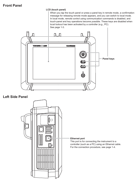
3. Remote/Local Mode Switching
Switching logic: When the PC sends the "COMMunicate: REMote ON" command, the device enters remote mode, and "Remote" is displayed at the top of the screen. At this time, touch panel/button operations can only trigger the "Release Remote Mode" confirmation pop-up window; Send "COMMunicate: REMote OFF" or click "OK" in the pop-up window to switch back to local mode.
Mode restriction: In remote mode, if the PC sends the ": Communicate: LOCKout ON" command, the local operation will be locked and can only be released through the PC command; When switching between two modes, the current device settings will be retained without the need for reconfiguration.
(2) USB interface
1. Core features and parameters
Function: Consistent with Ethernet interface function, supports remote command reception, data transmission, and status monitoring, but requires additional driver installation.
Technical specifications: 1 Mini Type B port, compliant with USB 2.0 standard, device in self powered mode; Only supports Windows 8.1/10/11 system PC, requires installation of Yokogawa USB driver (YKMUSB) and communication library (TMCTL); The waveform transmission rate is slightly higher than Ethernet, with a byte data transmission time of about 700ms for 1 million data points and about 25s for ASCII data.
2. Connection and configuration
Hardware connection: Use a USB Mini B cable to connect the USB port on the left panel of the device to the PC. If multiple devices are connected through a USB hub, connect the DL350 to the hub port near the PC to avoid signal attenuation; Do not plug or unplug USB cables within 20-30 seconds after the device is turned on (not fully started) to prevent damage to the device.
Parameter setting: Set "USB Function" to "TMC" through the device menu "Utility>System>Others". After setting, restart the device to take effect; PC requires the installation of corresponding drivers, which can be obtained through the official website or by contacting distributors. The use of third-party USB drivers is prohibited.
3. Remote/Local Mode Switching
Switching logic: Completely consistent with the Ethernet interface, confirm the switch through PC commands or local pop ups, and retain the current settings when switching modes.
Exclusive restriction: Ethernet and USB interfaces cannot be used simultaneously. When one interface is enabled, the other interface will be automatically disabled.
Fundamentals of Programming and Instruction System
(1) Core Programming Concepts
1. Message format
Program message: sent from a PC to a device, containing one or more instruction units separated by semicolons, and ending with a termination symbol (NL, ^ END, or NL ^ END); Each instruction unit consists of "program header+space+program data", such as "ACQuire: MODE NORMal" (set the acquisition mode to normal mode).
Response message: returned by the device to the PC, corresponding to the query instruction in the program message, in the format of "response header+space+response data" (some queries only return data), terminated with NL ^ END at the end; If the program message contains multiple queries, the response will be returned in the order of the queries.
2. Data type
Supporting multiple data formats to adapt to different control requirements, the key types and descriptions are as follows:
Example of Data Type Format Explanation
Decimal numbers (<Decimal>) consist of integers (NR1), fixed-point numbers (NR2), and floating-point numbers (NR3). The device can receive any format, and the response is uniformly set to NR3 with a sampling rate of "TIMebase: SRATE 1E6"
Physical quantities (such as<Voltage>/<Time>) are numerical values prefixed with units or multiples, and units/prefixes are not case sensitive. Set the timeline as "TIMebase: TDIV 1US"
Register>supports decimal, hexadecimal (# H), octal (# Q), and binary (# B), and responds by uniformly setting events in decimal: "STATus: EESE # H01"
Pre defined mnemonic for character data (<Character data>), to be selected from options, case insensitive setting coupling method: "CHANnel1: COUPling AC"
Boolean value (<Boolean>) supports ON/OFF or numerical values (0=OFF, non-zero=ON), and the response uniformly uses 0/1 to open the channel display: "CHANnel1: DISPlay ON"
The string (<String data>) needs to be enclosed in single/double quotation marks. If it contains quotation marks, two consecutive setting labels should be entered: "CHANnel1: LABel" CH1_TEST "
Block data (<Block data>) 8-bit binary data, formatted as "# N+N bit data length+data byte sequence", only used to respond to waveform data response: "# 800000010ABCDEFGHIJ"
(2) Instruction system
The manual divides instructions into 37 command groups, covering full remote control functions such as device acquisition, analysis, display, and triggering. The core command groups and functions are as follows:
Command Group Core Instruction Function Description
ACQuire Group: ACQuire: MODE, ACQuire: LENGTH Set/query waveform acquisition mode (normal/average/envelope), recording length (oscilloscope mode)
ANALysis Group :ANALysis:HARMonic:FREQuency、:ANALysis:HARMonic:RESult? Configure harmonic analysis frequency, query harmonic RMS/power analysis results (such as total distortion rate, active power)
CHANnel Group: CHANnel<x>: COUPling, CHANnel<x>: SCALe sets channel input coupling (AC/DC/GND), screen display upper and lower limits, supports voltage, temperature, strain and other modules
TRIGger Group: TRIGger: MODE, TRIGger: LEVel Configure trigger mode (single/repeated), trigger level, supports multiple trigger types such as edge, pulse width, etc
WAVeform Group :WAVeform:SEND? 、 WAVeform: FORMat queries waveform data and sets data transmission format (byte/word/ASCII)
SYSTem Group :SYSTem:CLOCk:DATE、:SYSTem:BATTery:REMain? Set device date and time, check battery remaining level
Common Command Group *IDN? 、 *CLS, OPC standard IEEE 488.2 command, query device model, clear status register, mark operation completed
Status monitoring and troubleshooting
(1) Status reporting mechanism
The device achieves status monitoring through status bytes, registers, and queues. The core components include:
Status byte: 8-bit binary data, reflecting the overall operating status of the device, such as bit0 indicating operation completion and bit5 indicating error occurrence.
Standard event register: records device standard events (such as operation completion, query errors), which can be enabled through "* ESE" and queried and cleared through "* ESR?".
Extended event register: records device specific events (such as collection completion, trigger occurrence), enabled through the "STATus: EESE" setting, cleared through the "STATus: EESR?" query.
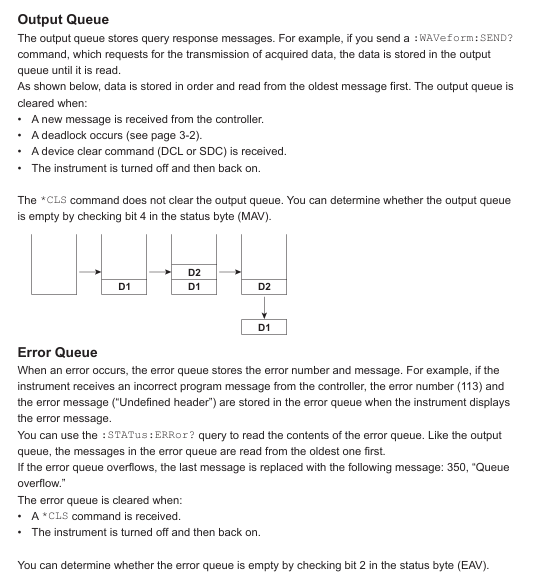
Output and Error Queue: The error queue stores the latest error code and description, which can be queried through "STATus: ERRor?"; The output queue stores non error messages, which can be set to be stored or not through ": STATus: QENable".
(2) Common problem solving
Troubleshooting steps for problem types and phenomena
Communication connection issue: Ethernet/USB cannot establish a connection. 1. Check if the cable connection is secure, and confirm if the Ethernet IP address is in the same network segment; 2. USB needs to confirm whether the driver is installed correctly and whether the device's "USB Function" is set to "TMC"; 3. Restart the device and PC and try again
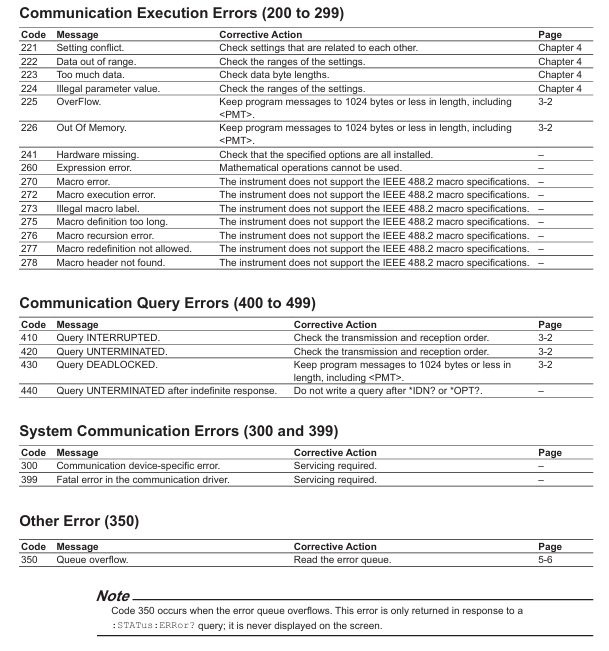
Instruction execution problem: Sending instructions without response or error. 1. Check the instruction syntax (such as case and parameter range), refer to Chapter 4 of the manual to confirm the instruction format; 2. Confirm that the device is in remote mode and there is no local lock; 3. Check the communication timeout setting. If the data volume is large, the timeout time can be extended
Data transmission issue: waveform data transmission interruption or distortion. 1. Confirm that the transmitted data format is consistent with the supported format of the device (such as byte/word/ASCII); 2. Ethernet needs to check network bandwidth to avoid transmitting large amounts of data simultaneously; 3. USB requires the use of short distance cables to reduce signal attenuation
- OMRON
- ABB
- General Electric
- EMERSON
- Honeywell
- HIMA
- ALSTOM
- Rolls-Royce
- MOTOROLA
- Rockwell
- Siemens
- Woodward
- YOKOGAWA
- FOXBORO
- KOLLMORGEN
- MOOG
- KB
- YAMAHA
- BENDER
- TEKTRONIX
- Westinghouse
- AMAT
- AB
- XYCOM
- Yaskawa
- B&R
- Schneider
- KONGSBERG
- NI
- WATLOW
- ProSoft
- SEW
- ADVANCED
- Reliance
- TRICONEX
- METSO
- MAN
- Advantest
- STUDER
- DANAHER MOTION
- Bently
- Galil
- EATON
- MOLEX
- DEIF
- B&W
- ZYGO
- Aerotech
- DANFOSS
- Beijer
- Moxa
- Rexroth
- Johnson
- WAGO
- TOSHIBA
- BMCM
- SMC
- HITACHI
- HIRSCHMANN
- Application field
- XP POWER
- CTI
- TRICON
- STOBER
- Thinklogical
- Horner Automation
- Meggitt
- Fanuc
- Baldor
- SHINKAWA
- Other Brands
- UniOP
- KUKA
- Iba
- Beckhoff
-
 Basler D90 96801 100 PCB Card
 -
 Basler XR2002F Voltage Regulator (110 VAC, 48-480 Hz)
 -
 Basler SR8A-2B14B3A Regulator
 -
 Basler 9561500100 Module
 -
 Basler DECS-400 BE1-11 System
 -
 Basler DECS-100-B15 Excitation Control
 -
 Basler SCP 210 Frequency Controller
 -
 Basler SR4A-2B15B3A Static Voltage Regulator
 -
 Basler BE1-32R Power Relay
 -
 Basler PIA2400-17GM Power Interface Adapter
 -
 Basler MVC 232 Manual Voltage Control Module
 -
 Basler SSR 32-12 Static Voltage Regulator
 -
 Basler 5MW AVR Generator Voltage Regulator
 -
 Basler VR63-4B Voltage Regulator
 -
 Basler DECS-100-A05 AVR for Engine Generator
 -
 Basler DECS-100-B15 Automatic Voltage Regulator
 -
 Basler BE1-32R Directional Power Relay
 -
 Basler BE1-87B Differential Relay
 -
 Basler UFOV 260A Protective Module
 -
 Basler 9-2614-02-100 PCB Rev M
 -
Basler DECS-100-B15 Digital AVR
-
 Basler 9284900103 PS DECS-400N
 -
 Basler D4N3H1U Intertie Protection
 -
 Basler DECS-100-B15 A15 AVR
 -
 Basler KR4F Voltage Regulator
 -
 Basler BE26434 T14 Transformer
 -
 Basler SR8A-2B15B3A Regulator
 -
 Westinghouse 774B472A12 AR Relay
 -
Basler DECS-100-B15 AVR
-
Basler XR2002F Regulator 110V
-
Basler SR125-E Static Regulator
-
 Basler SSR 125-12 Regulator
 -
 Basler MOC2599 Motor Pot
 -
 Basler BE1-DFPR Feeder Relay
 -
 Basler CBS 305 Current Boost
 -
 Basler BE1-25 AutoSync
 -
 Basler MVC 300 Voltage Control
 -
 Basler BE3-25A AutoSync
 -
 Basler KR7FF Static Regulator
 -
 Basler 90-49000-100 Regulator
 -
 Basler 880 kVA Dry Type Transformer Specs
 -
 Basler Electric BE1-25 Sync-Check Relay Specs
 -
 Basler SSR 125-12 Voltage Regulator Specs
 -
 Basler Electric BE1-851 Overcurrent Relay Review
 -
Basler Electric 149D930G02 Control Sub-Assembly
-
 Basler Electric BE1-81O/UT Frequency Relay Specs
 -
 Basler Electric BE1-51/27C Overcurrent Relay
 -
 Basler Electric 149D956G02 Industrial Component
 -
Basler Electric BE1-51A Overcurrent Relay Specs
-
 Basler Electric BE1-40Q Loss of Excitation Relay
 -
 Basler DECS-200 Excitation Control System
 -
 Basler DECS-200 Voltage Regulator 56-277V AC / 125V DC
 -
Basler BE1-87T Transformer Differential Relay
-
 Basler RDP-110-S1 Protection Relay
 -
 Basler BE1-700V Digital Protective Relay
 -
 Basler BE1-951 Overcurrent Protection System
 -
 Basler DECS-300 Digital Excitation Control
 -
 Basler DECS-200 Digital Excitation Control
 -
 Basler DECS-200-1C Excitation Control System
 -
Basler DECS-200-1L Digital Excitation Control
-
 Basler Electric BE1-GPS Generator Protection System
 -
Basler Electric DECS-200-1C Digital Excitation Controller
-
 Basler Electric DECS125-15 Excitation Control with Power Module
 -
 Basler Electric BE1-87G Differential Relay
 -
 Basler Electric BE1-11 Protection System I5A3M2P2N0EA00
 -
Basler Electric DECS-200-1C Excitation Control System
-
Basler Electric BE1-11g Generator Protection Relay
-
Basler Electric DECS 125-15-B2C1 V2.0.9 Excitation Control
-
 Basler Electric BE1-81O/UT3ED1JA7N2F Frequency Relay
 -
Basler Electric BE1-81O/UT3EE1YB7N1F Frequency Relay
-
 Basler Electric DECS-200-1L Digital Excitation Control System
 -
Basler DECS125-15-B2C1 Excitation Control
-
 Basler 9507900205 SSR Retrofit Voltage Regulator
 -
 Basler BE2000E Digital Voltage Regulator
 -
 Basler BE1-GPS Generator Protection System
 -
Basler DECS-250-CN1CN1N Digital Excitation Control
-
 Basler DGC-2020 Genset Controller
 -
 Basler BE1-81O UT3ED1LA7N0F Frequency Relay (Variant)
 -
 Basler BE1-81O UT3EE1YA9S0F Frequency Relay (Variant)
 -
Basler BE1-81O Over/Under Frequency Relay
-
Basler DECS125-15 Digital Excitation Control
-
Basler Electric BE1-951 Overcurrent Protection System
-
 Basler Electric BE1-700V Digital Protective Relay
 -
 Basler Electric APR63-5 Automatic Voltage Regulator
 -
Basler Electric BE1-851 Overcurrent Protection System
-
Basler Electric DECS-250-LN1SN1N Excitation Control
-
 Basler Electric BE1-87T Transformer Differential Relay
 -
Basler Electric DECS-200-1L Excitation Control System
-
 Basler Electric 9310300100 DECS-300 Excitation Control
 -
 Basler Electric SSE-N 125-4.5KW Shunt Exciter Regulator
 -
 Basler Electric DGC-2020HD-5NS1DNSBA Genset Controller
 -
Basler Electric BE1-81-O/UT3EE1JB7N1F Frequency Relay
-
Basler Electric BE1-81T1EE1WA0N1F Frequency Relay
-
 Basler Electric BE1-25M1EA6PN5R1F Sync-Check Relay
 -
 Basler Electric BE1-GPS Generator Protection System
 -
Basler Electric DECS-250-LN1SN1N Excitation Control Rev V
-
 Basler Electric DECS-250-CN2CN1N Excitation Control
 -
Basler Electric BE1-50/51B-207 Overcurrent Relay
-
Basler Electric DECS-300-C0N0 Excitation Control System
-
Basler Electric DECS-200 Digital Excitation Control System
-
Basler Electric DECS-250-LN1CN1N Excitation Unit
-
Basler Electric DECS-250 LN2SA1D Excitation Unit Specs
-
Basler Electric BE1-87T Transformer Relay Review
-
Basler Electric BE1-11 Protection System
-
Basler Electric BE1-GPS100-E4N1H1N Protection System
-
 Allen-Bradley 442G-MABH-R Safety Module
 -
 Beckhoff CX1030-0111 PLC Assembly Profile
 -
 FANUC IC693CPU364 PLC Module
 -
 Orange Denmark Type 200816 220 PLC Specs
 -
 OMRON C200H-SNT31 Sysmac PLC Module
 -
 Allen Bradley 20AB022A3AYNANC0 PowerFlex 70
 -
 OMRON C200HW-PCU01 Position Control Unit
 -
 ABB AO845A-eA Analog Output Module
 -
 OMRON CJ1M-CPU22 CPU Unit
 -
 Allen Bradley 100-E265ED11 Contactor
 -
 Honeywell 51304511-100 Interface Module
 -
 SOLEXY BXF3S0101N0018 Gateway Module
 -
 OMRON CJ2H-CPU65 CPU Unit
 -
 Automation Direct GS2-45P0 AC Drive
 -
 M68-2000 2-Axis Motion CNC Controller
 -
 OMRON CJ1M-CPU11 V3.0 PLC CPU Unit
 -
 OMRON CJ1W-NC413 4-Axis Positioning Controller
 -
 OMRON 3G2A3-PRO16 Programming Console HMI
 -
 Siemens 3VT8440-2AA04-2GA2 Molded Case Circuit Breaker
 -
 Siemens 3RT5045 Contactor Series
 -
 OMRON C200HS-CPU01-E SYSMAC PLC Controller
 -
 OMRON C500-NC103-E Positioning Control Unit
 -
 OMRON CJ1W-TC001 Temperature Control Unit


