
TRICON ®/ Installation and maintenance of E/E2/E3 transmitters
2 200 3 4.6080 15.36 0–200
3 450 5 2.8900 21.68 0–450
4 1000 10 1.5900 26.50 0–1000
6 2000 20 0.4640 15.47 0–2000
8(S/N≤31918014) 3500 35 0.2493 14.54 0–3500
8(S/N≥31918274) 3500 35 0.2253 13.14 0–3873
10(S/N≤31919282) 5500 50 0.1600 14.67 0–5500
10(S/N≥31919300) 5500 50 0.1472 13.49 0–5981
Note: E2 high-resolution output requires multiplying the number of pulses per gallon and the maximum flow pulse output value by 9, while E3 requires multiplying by 10
High Performance Turbine Meter (HPT)
Water meter size (inches) Continuous maximum flow rate (gpm) Minimum flow rate (gpm) Pulses per gallon Maximum flow rate Pulse output (Hz) 4-20mA Output flow range (gpm)
1½ 160 4 6.09500 16.25 0–160
2 200 4 6.09500 20.32 0–200
3 450 5 11.20000 84.00 0–450
4 1200 10 7.55600 151.1 0–1200
6 2500 20 0.72730 30.30 0–3000
8 4000 35 0.75560 50.37 0–4000
10 6500 50 0.75560 81.86 0–6500
12 8000 120 0.75560 100.75 0–8000
16 13500 200 0.07556 17.00 0–13500
20 22000 300 0.07556 27.71 0–22000
Note: The high-resolution output coefficient is the same as Trident's ® Turbine watch
Compound Meters
Core composition: Composed of a combination of turbine components and disk components, the components of different models of composite watches are matched differently (such as 3 "TRU/FLO consisting of 3" TT turbine components and ⅝ "T-10 disk components).
Performance reference: It is necessary to separately refer to the performance specifications of the corresponding turbine components and disc components. The 4 "/6"/8 "/10" HP TECTUS III turbine components have dedicated performance parameter tables.
Installation process
Pre-installation preparation
Tools and Materials
Essential tools: Medium sized flathead screwdriver, wire stripping pliers, hammer, ⅛ "diameter punch (or similar tools).
Essential material: # 22 AWG multi-core solid copper wire.
Optional material: Dow Corning ® # 4 moisture-proof compounds (or equivalent products).
Inspection and Storage
After unboxing, check whether the transmitter components (including the transmitter body, terminal cover, and installation ring) are intact, without damage or missing.
Before installation, the components need to be stored in a clean and dry environment, with a temperature maintained between -40 ° C and 85 ° C.
Safety and wiring specifications
Avoid placing instrument circuits near electrical noise sources such as contactors, motor starters, radio transmitters, and high-voltage power lines.
Separate the wiring of instrument circuits from other circuits and prioritize the use of independent metal conduits or metal cable trays; Long distance cabling (up to 1000 feet) requires # 22 AWG shielded twisted pair cables, with the shielding layer only grounded at the receiving device end.
When wiring needs to intersect, maintain a right angle intersection to reduce noise coupling; Use dedicated power sources (such as independent circuit breakers, isolation transformers) to ensure grounding in accordance with local electrical regulations.
Specific installation steps
1. Wiring operation
Unscrew the terminal cover screws, remove the terminal cover, thread the multi-core cable through the hole on the terminal cover, and move the terminal cover down along the cable to a convenient operating position.
Peel off the outer sheath of the cable by about 1.5 inches, separate the core wires and strip off the insulation layer of each core wire by about 0.5 inches. Use a screwdriver with a round handle to bend the bare copper wire into a hook shape.
Loosen the terminal screw of the transmitter, and wrap the hooks of each core wire clockwise around the corresponding terminal screw according to the wiring diagram (ensuring that the insulation layer is not pressed under the screw), and tighten the screw firmly (avoiding over tightening).
2. Wiring code (divided by pins)
Pin number TRICON ®/ E digital pulse type (before January 1996) TRICON ®/ E2/E3 digital pulse type (after January 1996) TRICON ®/ E/E2/E3 4-20mA type
1 connectionless high-resolution output 4-20mA source (+)
2 unconnected counting direction (ground contact closed, powered by pull-up resistor) 4-20mA return (-)
3 12-24VDC power input (+) 12-24VDC power input 24VDC power input (+)
4 Public Grounding (-) Public Grounding (-) Public Grounding (-)
5 pulse output pulse output pulse output
Note: The typical value of the pull-up resistor is 2K Ω for every 5VDC; "+" indicates that the regular current flows out of the transmitter.
3. Line testing
Connect the transmitter power and verify the output signal according to the following standards:
When there is no flow: there is no pulse at the digital output terminal, and the 4-20mA circuit current is 4mA.
At half flow rate: the pulse frequency of the digital output terminal is 1/2 of the maximum pulse frequency, and the 4-20mA circuit current is 12mA.
At maximum flow rate: The pulse frequency of the digital output terminal is equal to the maximum pulse frequency, and the 4-20mA circuit current is 20mA.
4. Final assembly
Turn off all power and apply sufficient Dow Corning on exposed wires and terminals ® # 4 compounds, the interior of the terminal cover is also filled with this compound (for moisture resistance).
- ABB
- General Electric
- EMERSON
- Honeywell
- HIMA
- ALSTOM
- Rolls-Royce
- MOTOROLA
- Rockwell
- Siemens
- Woodward
- YOKOGAWA
- FOXBORO
- KOLLMORGEN
- MOOG
- KB
- YAMAHA
- BENDER
- TEKTRONIX
- Westinghouse
- AMAT
- AB
- XYCOM
- Yaskawa
- B&R
- Schneider
- KONGSBERG
- NI
- WATLOW
- ProSoft
- SEW
- ADVANCED
- Reliance
- TRICONEX
- METSO
- MAN
- Advantest
- STUDER
- DANAHER MOTION
- Bently
- Galil
- EATON
- MOLEX
- DEIF
- B&W
- ZYGO
- Aerotech
- DANFOSS
- Beijer
- Moxa
- Rexroth
- Johnson
- WAGO
- TOSHIBA
- BMCM
- SMC
- HITACHI
- HIRSCHMANN
- Application field
- XP POWER
- CTI
- TRICON
- STOBER
- Thinklogical
- Horner Automation
- Meggitt
- Fanuc
- Baldor
- SHINKAWA
- Other Brands
- UniOP
- KUKA
- Iba
-
 ABB 3BUS208720-001 Industrial Power Signal Interconnection Module
 -
 TMEIC KPAD-3122A LCD Display Keypad
 -
 Siemens 6SN1145-1BA02-0CA1 PLC
 -
 LAM 2004365 TURBO BYPASS PLC ASM
 -
 Omron CJ1W-CORT21 PLC Module
 -
 Euchner MGB-L2B-PNA-L-121853 Safety Switch
 -
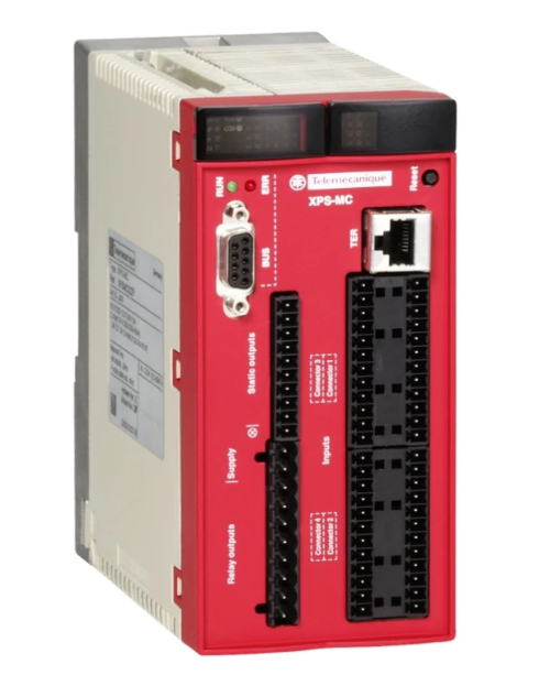 XPSMC32ZP Safety Controller
 -
 Schneider 9070T3000D33 PLC
 -
 Omron C200H-MAD01 AD DA Module
 -
 Omron NJ501-1320 CPU Controller
 -
 Honeywell C36TR1UA1000 Thermostat
 -
 Honeywell TC-RPDXX1 Power Supply Module
 -
 Fuji NW0E32-3 PLC Programmable Controller
 -
 ASM 2004219 Turbo Bypass ASM 107864 Module
 -
 Future IHDW-BLA4S-IM CNC MPG Handwheel
 -
 Wieland R1.180.0080.0 SA-OR-S1-4RK-A Safety Module
 -
 Reliance Electric 57C493 AutoMax Power Supply 376W
 -
 Siemens 3VT8563-2AA03-2KA2 MCCB 3VT8
 -
 B&R X20IF1072 CAN Bus Interface Module
 -
 Mitsubishi OSE253S2 Rotary Encoder
 -
 Mitsubishi NV630-SW 4P 500A Earth Leakage Breaker
 -
 Euchner MGB-L1B-PNA-R-121857 Safety Switch
 -
 Honeywell 900A01-0102 Analog Input Module
 -
 OMRON C500-ID219 Input Unit
 -
 Westinghouse EL3030R Current Limiter
 -
 CLA-2 3L Electric Lubrication Pump
 -
 Proface GP2501-TC41-24V HMI
 -
 Omron KM-N1-FLK Small Power Monitor
 -
 HPM 1D703-0040 Command 9000 Console Card
 -
 Siemens 3RW5074-6AB14 SIRIUS Soft Starter
 -
 Genie 75032 Limit Switch
 -
 OMRON C200H-SP001 Space Module
 -
 OMRON C200H-PS211 Power Supply Unit
 -
 OMRON C200H-OC222 Relay Output Unit
 -
 Keyence KV-8000SO 4221 CPU Module
 -
 Cincinnati Milacron 3-542-1079A Circuit Board
 -
 Beckhoff EL3124 Analog Input EtherCAT Terminal
 -
 KRONES BWU1703 0900853537 ASi PROFIBUS Gateway
 -
 Radio Energie RE0444 R1S 0.06 CA Tachogenerator
 -
 Mitsubishi GT1685M-STBA GOT1000 HMI
 -
 Siemens 6GK7342-5DA03-0XE0 CP 342-5 PROFIBUS
 -
 Allen Bradley 8520-PX-ASM3-EXEC2-63M Servo Module
 -
 Delta AH10PM-5A Programmable Controller
 -
 Siemens 3TK2805-0BB4 Safety Contactor Combination
 -
 EUCHNER HBA-079827 Pendant Station
 -
 CLC-2 4L PLC Lubrication Pump
 -
 KEYENCE GS-51P5 Safety Switch
 -
 AB 442G-MABH-R Safety Switch
 -
 GE Fanuc VersaMax PLC Module Set
 -
 Siemens 6ES7214-1HF40-0XB0 CPU 1214FC
 -
 Microchip DSPIC30F4011-30I/P DSC
 -
 FANUC A20B-2102-0081 I/O Link Module
 -
 Endress Hauser CLS15-B1M2A Conductivity Sensor
 -
 B&R 3AM050.6 Analog I/O Module
 -
 Fanuc A16B-2201-0320 MAIN-B CPU Board
 -
 Pilz 475650 PNOZ 1 Safety Gate Relay
 -
 Omron NSH5-AL001 Handheld HMI Terminal
 -
 Allen-Bradley 1756-OF8 Analog Output 8 Ch
 -
 Siemens 6SL3210-1SE31-0AA0 45kW Power Module
 -
 PMA TB45-110-00000-000 Temperature Limiter
 -
 PSR-SCP-24DC-ESD-5x1-1x2-300 Safety Relay
 -
 Pilz 774140 PZE 9 24V AC Safety Relay
 -
 Telemecanique TSXRKN82F 8 Slot Rack
 -
 Mitsubishi R16CPU iQ-R PLC CPU
 -
 Mitsubishi A2ACPU-R21-S1 PLC CPU
 -
 Omron NX-AD4208 Analog Input Unit
 -
 Schneider LMC802CAA10000 PacDrive 3 Controller
 -
 Reliance Electric 0-51874 Static Sequence Card
 -
 Pilz 787310 PNOZ X3P C Safety Relay
 -
 B&R X20CP1684 CPU Module
 -
 Siemens 6SN1145-1BB00-0FA1 Power Module
 -
 Beckhoff EL3174 Analog Input EtherCAT Terminal
 -
 CLC-2P 4L PLC Lubrication Pump System
 -
 Omron CJ1W-DA08C Analog Output Unit
 -
 Metso Automation D201776 ACN PO DC PLC Control Server Computer
 -
 GE AT868 AquaTrans Ultrasonic Flow Transmitter
 -
 ABB PFSA107-Z42 DTU Stressometer Digital Transmission Unit
 -
 ABB PFSA240 3BSE073476R1 Roll DC Supply Unit
 -
 Fanuc A16B-2201-0320 CPU MAIN Board
 -
 Pilz 475650 PNOZ 1 Safety Gate Relay
 -
 Omron NSH5-AL001 HMI Interface Unit
 -
 Allen-Bradley 1756-OF8 Analog Output Module
 -
 Siemens 6SL3210-1SE31-0AA0 Power Module 45kW
 -
 PMA TB45-110-00000-000 Temperature Limiter
 -
 PSR-SCP-24DC-ESD-5x1-1x2-300 Safety Relay
 -
 Pilz 774140 PZE 9 Safety Relay
 -
 Telemecanique TSXRKN82F PLC Rack Chassis
 -
 Mitsubishi R16CPU PLC CPU Module
 -
 OMRON C500-PS223-E Power Supply Module
 -
 Siemens 3VL4731-1DC36-0AA0 Circuit Breaker
 -
 Siemens 7ML5201-0EA0 Ultrasonic Level Transmitter
 -
 OMRON NQ3 NQ5 Touch Panel HMI
 -
 OMRON CJ1W-AD081-V1 Analog Input Module
 -
 OMRON NJ301-1100 Machine Automation Controller
 -
 B&R X20BC00G3 EtherCAT Bus Controller
 -
 Schneider ATV212HD22N4S Variable Speed Drive
 -
 B&R 8B0C0320HW00.002-1 Power Supply Module
 -
 Mitsubishi OSA105S2A Incremental Rotary Encoder
 -
 Pilz 777514 PNOZ XV3P Safety Relay
 -
 Gould AS-884A-111 Modicon 884 Controller
 -
 Siemens 6SC6130-0FE00 SIMODRIVE Control Card
 -
 Omron CV500-PS221 PLC Power Supply Module
 -
 ABB CM577-ETH AC500 PLC Ethernet Module
 -
 Omron NX-SIH400 Safety Input Unit NX Series
 -
 Omron NJ501-1300 Machine Automation Controller
 -
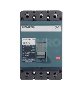
 Siemens 3VT8563-2AA03-2KA2 Molded Case Breaker
 -
 Pilz PNOZ m1p ETH 773103 Safety Controller
 -
 Omron CJ1H-CPU66H-R CJ1 Series CPU Module
 -
 ASI ASI533-S00 PLC Module S1
 -
 Mitsubishi AJ71C21-S1 Serial Module
 -
 Keyence IX-1000 Laser Sensor Amplifier
 -
 Siemens 6SN1145-1AA01-0AA1 Power Module
 -
 Siemens 3VA2340-5HL32-0AA0 MCCB 400A
 -
 Mitsubishi OSA104S Absolute Encoder
 -
 Siemens 6ES7350-1AH03-0AE0 FM 350-1 Counter
 -
 Siemens 6SE7038-6EK84-1JC2 IGD8 Gate Driver
 -
 Eaton EASY819-AC-RC Programmable Relay
 -
 Omron CPM1A-40CDT-D PLC 24V DC
 -
 Omron NA5-12W101B-V1 12-inch Programmable Terminal
 -
 Siemens 6ES7331-7KF02-0AB0 Analog Input SM 331
 -
 Moxa PTC-101-S-SC-HV Photoelectric Converter
 -
 Fanuc A20B-3300-0031 CNC Control Circuit Board
 -
 OMRON NA5-7W001B-V1 Programmable Terminal HMI
 -
 Parker AH385851U002 590C DC Drive Power Board
 -
 ABB 3BSE040662R1 AI830A Analog Input Module
 -
 DOLD BF9250.01/001 Solid State Relay
 -
 Siemens 6ES7331-7KF02-0AB0 SIMATIC S7-300 SM 331
 -
 ABB 07AC91 I6 GJR5252300R3101 Advant Controller 31


