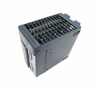
SIEMENS G120 CU240BE-2 frequency converter
SIEMENS G120 CU240BE-2 frequency converter
Detailed analysis of parameter system
(1) Basic rules for parameters (supplementary configuration logic)
Parameter number and type
Number format: Read and write parameters starting with "p" (such as p0003), read-only parameters starting with "r" (such as r0002, displaying the running status of the driver);
Index identifier: with [0... n] indicating multiple index parameters (such as p0304 [0... n], supporting storage of multiple motor parameters);
Bit field identifier: with. 0... n represents bit parameters (such as r0046.0, corresponding to the switch status of specific functions).
Parameter access and modification rules
Access level control: Set through P0003, Level 3 (expert level) includes 1-2 levels of functionality, and Level 4 (service level) requires a password (p3950) to unlock;
Modification effective conditions: Some parameter annotations "C (x)" indicate that they can only be modified in debugging mode (p0010=x), "U" indicates that they can be modified during operation, "T" indicates that they can be modified in the ready state, and some parameter modifications require restarting the frequency converter to take effect;
The impact of associated parameters: The "Linked parameterization" feature automatically synchronizes the modification of associated parameters when modifying some parameters (such as p0922 PROFIBUS telegram), and the impact range needs to be confirmed in advance.
(2) Detailed analysis of core parameter module
1. Basic configuration parameters (p0000-p0999)
Parameter Number Parameter Name Core Function Value Range Default Values Key Explanation
The parameter range that can be viewed/modified in the access level control of P0003 is 3 (expert), 4 (service), and 3/4. The password p3950 is required for level 4, and only authorized service personnel can operate it
P0010 Debugging parameter filter filters visible parameters at different debugging stages 0-95 1 0=ready, 1=fast debugging, 3=motor debugging, 15=dataset configuration, 30=parameter reset, 95=safety integration debugging
P0015 Driver Unit Macro Run Preset Macro File, Quickly Configure Typical Application Scenarios 0-999999 7 (CU240B-2)/12 (CU240E-2) After Execution, Parameter Lock, R3996=0 is Required to Modify Again
P0096 Application class switching control view (adapted to different application scenarios) 0=Expert, 1=Standard drive control, 2=Dynamic drive control 0 1=Suitable for standard loads such as pumps/fans, 2=Suitable for high dynamic response loads (such as machine tools)
P0100 Standard Selection (IEC/NEMA) Switching Motor Parameter Unit System 0=IEC, 1=NEMA, 2=NEMA+SI 0 0=Power Unit kW, Frequency 50Hz; 1=Power Unit hp, Frequency 60Hz
P0170 Command Dataset Quantity (CDS) Configuration: The number of storable command datasets is 2-4. 2 Supports quick switching of different control commands (such as manual/automatic frequency source switching)
P0180 Driver Dataset Quantity (DDS) Configuration: The number of storable driver datasets ranges from 1 to 4, and supports fast switching of different motor or load parameters (such as multiple motors sharing a frequency converter)
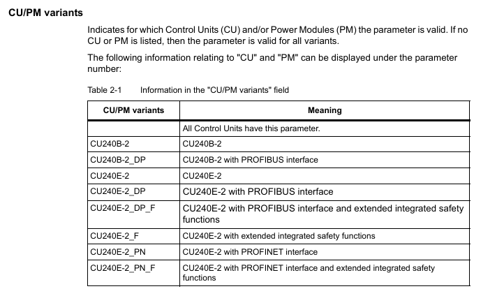
2. Motor parameters (p0300-p0399)
The core is used to match the motor nameplate data, which directly affects the control accuracy and protection function, and is a key debugging step:
Parameter Number Parameter Name Core Function Value Range Default Values Key Explanation
P0300 Motor type selection definition: Motor type 0=no motor, 1=induction motor, 2=synchronous motor, etc. After selecting 0, the corresponding motor parameters will be automatically filtered. If the synchronous motor does not display the exclusive parameters of the induction motor
P0301 motor code number: Select motor model 0-65535 from the built-in motor parameter list. 0=manually input parameters,>0=load preset parameters from Siemens motor database
The rated voltage input on the motor nameplate of P0304 motor is 0-20000 Vrms, which needs to be matched with the supply voltage. When connected in a star/delta configuration, it needs to be adjusted accordingly (such as the delta connection voltage being √ 3 times that of the star configuration)
The rated current input on the motor nameplate of P0305 motor is 0.00-10000 Arms 0.00, which directly affects the overcurrent protection threshold (p2100). Setting the wrong value may cause protection to trigger incorrectly or the motor to burn out
P0307 motor rated power input: The rated power on the motor nameplate is 0.00-100000 kW. The IEC standard unit is kW, and the NEMA standard unit is hp (when P0100=1)
P0310 motor rated frequency input: The rated frequency on the motor nameplate is 0.00-650.00 Hz. The default is 50Hz (IEC)/60Hz (NEMA), which affects the speed calculation (n=60f/p, p is the number of pole pairs)
The rated speed input on the nameplate of the P0311 motor ranges from 0.0 to 210000 rpm. 0.0 is used as the reference value for speed closed-loop control and, together with P0310, determines the number of motor poles (r0313)
P0340 automatically calculates parameters based on nameplate data to automatically calculate motor equivalent circuit parameters and control parameters 0-50 1=complete calculation, 2=motor parameter calculation, 3=closed-loop control parameter calculation, 4=controller parameter calculation, 5=threshold calculation
- EMERSON
- Honeywell
- CTI
- Rolls-Royce
- General Electric
- Woodward
- Yaskawa
- xYCOM
- Motorola
- Siemens
- Rockwell
- ABB
- B&R
- HIMA
- Construction site
- electricity
- Automobile market
- PLC
- DCS
- Motor drivers
- VSD
- Implications
- cement
- CO2
- CEM
- methane
- Artificial intelligence
- Titanic
- Solar energy
- Hydrogen fuel cell
- Hydrogen and fuel cells
- Hydrogen and oxygen fuel cells
- tyre
- Chemical fiber
- dynamo
- corpuscle
- Pulp and paper
- printing
- fossil
- FANUC
- Food and beverage
- Life science
- Sewage treatment
- Personal care
- electricity
- boats
- infrastructure
- Automobile industry
- metallurgy
- Nuclear power generation
- Geothermal power generation
- Water and wastewater
- Infrastructure construction
- Mine hazard
- steel
- papermaking
- Natural gas industry
- Infrastructure construction
- Power and energy
- Rubber and plastic
- Renewable energy
- pharmacy
- mining
- Plastic industry
- Schneider
- Kongsberg
- NI
- Wind energy
- International petroleum
- International new energy network
- gas
- WATLOW
- ProSoft
- SEW
- wind
- ADVANCED
- Reliance
- YOKOGAWA
- TRICONEX
- FOXBORO
- METSO
- MAN
- Advantest
- ADVANCED
- ALSTOM
- Control Wave
- AB
- AMAT
- STUDER
- KONGSBERG
- MOTOROLA
- DANAHER MOTION
- Bently
- Galil
- EATON
- MOLEX
- Triconex
- DEIF
- B&W
- ZYGO
- Aerotech
- DANFOSS
- KOLLMORGEN
- Beijer
- Endress+Hauser
- MOOG
- KB
- Moxa
- Rexroth
- YAMAHA
- Johnson
- Westinghouse
- WAGO
- TOSHIBA
- TEKTRONIX


Email:wang@kongjiangauto.com

