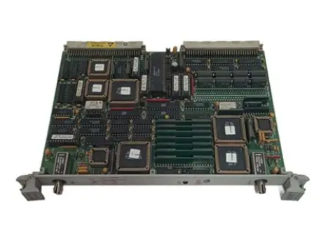
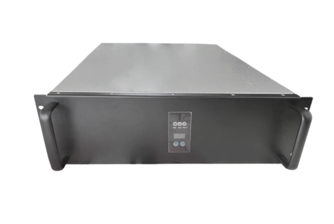
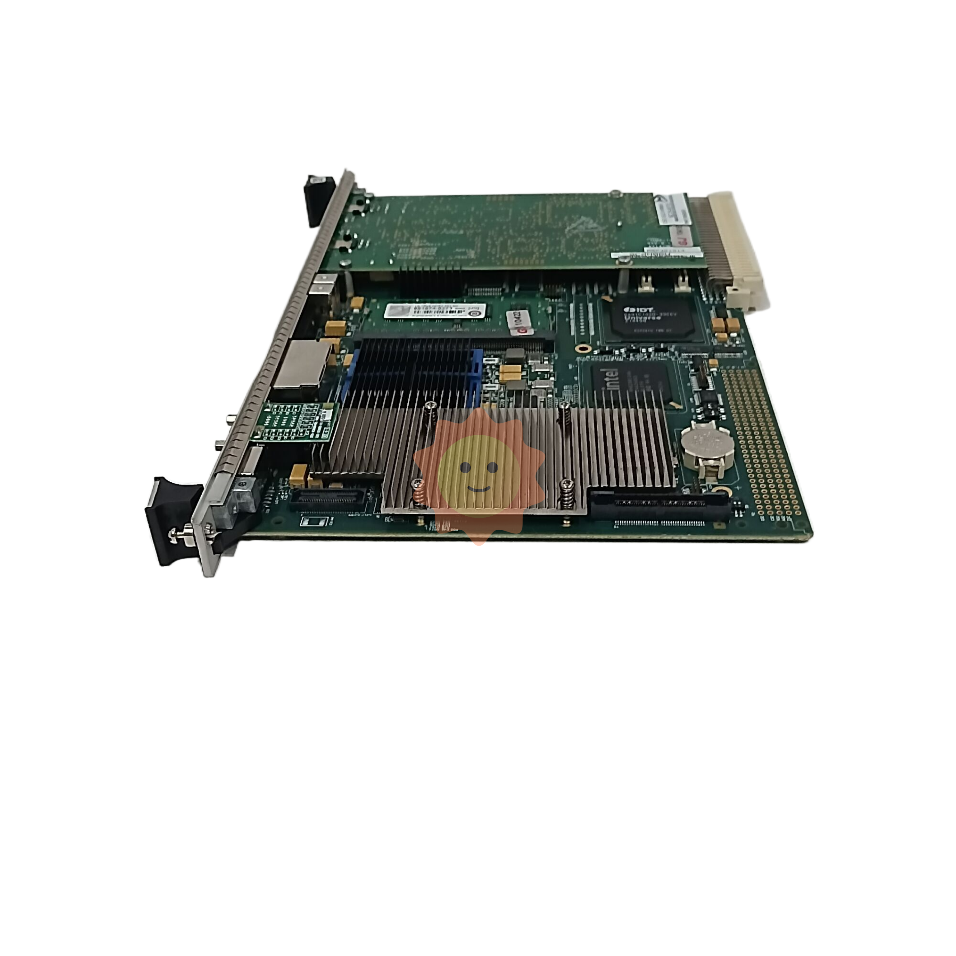
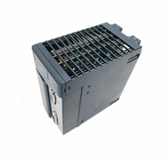
SIEMENS G120 CU240BE-2 frequency converter
3. Control mode and speed parameters (p1000-p1999)
Parameter Number Parameter Name Core Function Value Range Default Values Key Explanation
P1000 frequency setting source selection frequency converter output frequency control mode 0-10 2 0=none, 1=terminal, 2=analog, 5=communication, 7=PID, 10=process controller
P1080 Minimum output frequency limit: The minimum output frequency of the frequency converter is 0.00-600.00 Hz to prevent overload during low-speed operation of the motor (such as pump loads to avoid idling)
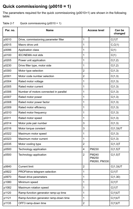
P1082 Maximum output frequency limit: The maximum output frequency of the frequency converter should not exceed 1.2 times the rated frequency of the motor (p0310), from 0.00-600.00 Hz to 50.00/60.00 Hz, to avoid motor overspeed damage
P1120 Acceleration time from 0 to maximum frequency rise time 0.01-6500.0 s 10.0 The greater the load inertia, the longer the acceleration time needs to be to prevent overcurrent tripping
The descent time from maximum frequency to 0 for p1121 deceleration time is 0.01-6500.0 s 10.0, which needs to be matched with the load braking demand. For large inertia loads, the deceleration time needs to be extended or braking resistors need to be configured
P1300 control mode selection: The core control algorithm of the frequency converter is 0-22. 20=V/f control, 20=vector control (without encoder), 21=vector control (with encoder), 22=torque control
P1900 motor recognition automatically identifies motor equivalent circuit parameters, optimizes control accuracy 0-3 20=disabled, 1=static recognition, 2=dynamic recognition (motor idling required), 3=precise recognition
4. Fault protection parameters (p2100-p2299)
Parameter Number Parameter Name Core Function Value Range Default Values Key Explanation
P2100 overcurrent protection threshold setting: The upper limit of overcurrent protection current is 1.0-2.0 times the rated current, and 1.5 times the rated current. If the threshold is exceeded, the frequency converter will immediately trip to avoid damage to the power module
P2175 overvoltage protection threshold setting DC bus overvoltage protection threshold 1.0-1.3 times rated voltage 1.15 times suitable for voltage fluctuation scenarios in the power grid. If the threshold is too high, it may cause capacitor damage
P2176 undervoltage protection threshold setting DC bus undervoltage protection threshold 0.7-0.9 times rated voltage 0.85 times lower than the threshold, the frequency converter will operate at reduced capacity or trip to prevent insufficient motor torque
P2200 motor overheat protection enable/disable motor overheat protection function 0=disable, 1=enable 1 Based on motor temperature model (p0612) or temperature sensor signal, rated or tripped when overheated
P2260 torque limit motor output torque 0.0-200.0% 150.0% to prevent motor damage caused by load overload, which needs to be adjusted according to the rated torque of the load
5. Communication parameters (p2000-p2099)
Parameter Number Parameter Name Core Function Value Range Default Values Key Explanation
P2010 communication address (PROFIBUS/Modbus) setting: The address 1-126 of the frequency converter in the communication network should be consistent with the configuration of the upper computer (PLC/HMI) to avoid address conflicts
P2023 Communication Baud Rate (Modbus) Set the transmission rate of Modbus communication to 9600/19200/38400/115200 bps. The higher the baud rate, the faster the transmission speed, but it is limited by the communication distance (such as 115200bps, recommended distance<10m)
P2080 PROFIdrive status word mapping configuration for PROFIBUS/PROFINET status word signal source 0-65535 0 defines the operating status signals (such as ready, fault, running) fed back by the frequency converter to the PLC
P2081 PROFIdrive control word mapping configuration PROFIBUS/PROFINET control word signal source 0-65535 0 defines the control commands sent by PLC to the frequency converter (such as start stop, frequency setting, fault reset)
6. Input/Output (I/O) Parameters (p0700-p0799)
Parameter Number Parameter Name Core Function Value Range Default Values Key Explanation
P0700 Definition of Digital Input Function Allocation: Functions of Digital Input Terminals (DI) 0-99 2 0=No Function, 1=ON/OFF 1, 2=ON/OFF 2 (Emergency Stop), 3=ON/OFF 3 (Quick Stop)
P0730 Digital Output Function Allocation (DO0) defines the function of the digital output terminal (DO0) from 0 to 99. 52.0 0=no function, 52.0=ready state, 52.3=fault state, 52.7=alarm state
P0756 Analog Input Type (AI0/AI1) Set the signal type of the analog input terminal to 0-8 4 0=0-10V voltage input, 2=0-20mA current input, 3=4-20mA current input, 4=-10V~+10V bipolar voltage
P0771 Analog Output Function Allocation (AO0) defines the signal source 0-99 of the analog output terminal (AO0). 21.0 0 0=no function, 21.0=output frequency, 27.0=output current, 28.0=output voltage
(3) Read only parameters and status monitoring (r series)
The manual provides a detailed list of R-series read-only parameters for real-time monitoring of equipment operation status. The core parameters are as follows:
R0002: Driver operating status (e.g. 0=everything is normal, 10=need to activate set value, 35=need initial debugging);
- EMERSON
- Honeywell
- CTI
- Rolls-Royce
- General Electric
- Woodward
- Yaskawa
- xYCOM
- Motorola
- Siemens
- Rockwell
- ABB
- B&R
- HIMA
- Construction site
- electricity
- Automobile market
- PLC
- DCS
- Motor drivers
- VSD
- Implications
- cement
- CO2
- CEM
- methane
- Artificial intelligence
- Titanic
- Solar energy
- Hydrogen fuel cell
- Hydrogen and fuel cells
- Hydrogen and oxygen fuel cells
- tyre
- Chemical fiber
- dynamo
- corpuscle
- Pulp and paper
- printing
- fossil
- FANUC
- Food and beverage
- Life science
- Sewage treatment
- Personal care
- electricity
- boats
- infrastructure
- Automobile industry
- metallurgy
- Nuclear power generation
- Geothermal power generation
- Water and wastewater
- Infrastructure construction
- Mine hazard
- steel
- papermaking
- Natural gas industry
- Infrastructure construction
- Power and energy
- Rubber and plastic
- Renewable energy
- pharmacy
- mining
- Plastic industry
- Schneider
- Kongsberg
- NI
- Wind energy
- International petroleum
- International new energy network
- gas
- WATLOW
- ProSoft
- SEW
- wind
- ADVANCED
- Reliance
- YOKOGAWA
- TRICONEX
- FOXBORO
- METSO
- MAN
- Advantest
- ADVANCED
- ALSTOM
- Control Wave
- AB
- AMAT
- STUDER
- KONGSBERG
- MOTOROLA
- DANAHER MOTION
- Bently
- Galil
- EATON
- MOLEX
- Triconex
- DEIF
- B&W
- ZYGO
- Aerotech
- DANFOSS
- KOLLMORGEN
- Beijer
- Endress+Hauser
- MOOG
- KB
- Moxa
- Rexroth
- YAMAHA
- Johnson
- Westinghouse
- WAGO
- TOSHIBA
- TEKTRONIX


Email:wang@kongjiangauto.com

