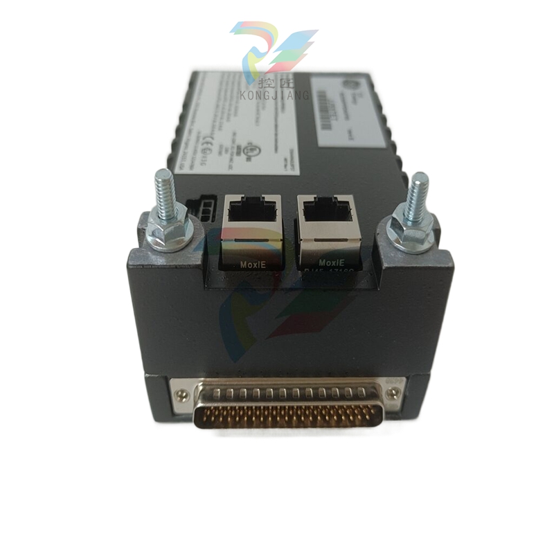
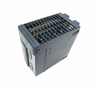
SIEMENS G120 CU240BE-2 frequency converter
R0021: Actual speed (smoothed), in rpm, reflecting the real-time speed of the motor;
R0025: Output voltage (smoothed), in Vrms, monitor the output voltage of the frequency converter;
R0027: Output current (smoothed), in Arms, to determine if the motor is overloaded;
R0031: Actual torque (smoothed), in Nm, reflecting the magnitude of the load torque;
R0052: Status word 1, displaying device ready, running, fault and other statuses through bit fields (such as bit0=ready, bit3=fault);
R0207: Rated current of power unit, reflecting the rated capacity of the inverter hardware;
R2135: Fault/alarm status word, records current or historical fault codes.
(4) Functional diagrams and logical associations
Chapter 3 of the manual provides detailed 590 page functional diagrams, covering:
Input/output terminal wiring logic (such as signal flow direction of DI/DO/AI/AO);
PROFIdrive communication protocol interaction logic (PROFIBUS/PROFINET data frame structure);
Control mode logic (such as speed closed-loop and torque closed-loop processes of vector control);
Fault protection logic (such as detection and tripping processes for overcurrent and overvoltage);
BICO parameter interconnection logic (such as the signal correlation between BI parameters and BO parameters).
Functional diagrams use standardized symbols to label parameter numbers and signal flow directions, helping technicians understand the underlying logic of parameter configuration. For example, the "speed control closed-loop" diagram clarifies the complete process of comparing r0021 (actual speed) and p1070 (speed set value), PID regulation, and output drive.
(5) Troubleshooting and Alarm Handling (Chapter 4)
Fault/alarm classification
Faults: The equipment cannot operate normally and needs to be manually reset after troubleshooting (such as F30002=DC bus overvoltage);
Alarm: The device can still operate but there are abnormalities that need attention (such as A07012=motor overheating warning).
Troubleshooting process
Step 1: Read the fault code through r2135 or the operation panel;
Step 2: Search the manual for the corresponding cause of the fault code (such as F30005=power unit I2t overload);
Step 3: Check according to the manual recommendations (such as checking if the load is overloaded and if the heat dissipation is good);
Step 4: Modify the corresponding parameters (such as adjusting the p2260 torque limit) or reset after fixing hardware faults.
Common faults and troubleshooting examples
F30002 (DC bus overvoltage): The reason may be that the grid voltage is too high and the deceleration time is too short; The processing method is to adjust the overvoltage threshold of p2175, extend the deceleration time of p1121, and configure the braking resistor;
F30005 (power unit I2t overload): The reason may be continuous overload of the load or a malfunction of the cooling fan; The processing method is to reduce the load, check the fan, and adjust the p0290 overload response strategy;
F07011 (motor overheating): The possible reasons may be excessive motor load or temperature sensor malfunction; The processing method is to reduce the rated operation, check the sensor, and adjust the P0605 overheating threshold.
Example of Key Application Scenario Parameter Configuration
Scenario 1: Pump/Fan Load (Standard Drive Control, p0096=1)
Basic configuration: p0010=1 (quick debugging) → p0300=1 (induction motor) → Input p0304/p0305/p0307/p0310 (motor nameplate data);
Control mode: p1000=2 (analog frequency source) → p1300=0 (V/f control);
Protection configuration: p2200=1 (motor overheating protection) → p2260=110% (torque limit);
Operating parameters: p1080=1.0Hz (minimum frequency anti slip) → p1120=30s (extended acceleration time waterproof hammer) → p1121=30s (extended deceleration time);
Confirm save: p3900=1 (complete quick debugging) → Parameters automatically take effect.
Scenario 2: Machine tool spindle load (dynamic drive control, p0096=2)
Basic configuration: p0010=1 → p0300=1 → Input motor nameplate data → p1900=2 (dynamic motor recognition);
Control mode: p1000=5 (communication frequency source) → p1300=20 (vector control without encoder);
Dynamic parameters: p1400=3.0 (PID proportional coefficient) → p1401=0.1 (PID integration time) → optimized dynamic response;
Protection configuration: p2100=1.8 (overcurrent threshold) → p2260=150% (torque limit) → p2175=1.2 (overvoltage threshold);
Communication configuration: p2010=5 (communication address) → p2080=1 (status word mapping) → p2081=1 (control word mapping);
Confirm save: p3900=2 → Restart the frequency converter to take effect.
Precautions and Risk Warning for Use
Before parameter configuration:
Confirm the control unit model and firmware version (r0018) to ensure parameter compatibility;
Disconnect the motor load or ensure that the load is in a safe state to avoid accidental operation of the equipment during debugging;
Backup the original parameters (p0971=1) for easy recovery in case of configuration errors.
In parameter configuration:
Strictly input the parameters p0300-p0311 according to the motor nameplate, incorrect settings may cause the motor to burn out;
Parameters related to safety functions (such as p0930 safety integration parameters) need to be configured by authorized personnel, and failure to comply with safety standards may result in personal injury;
- EMERSON
- Honeywell
- CTI
- Rolls-Royce
- General Electric
- Woodward
- Yaskawa
- xYCOM
- Motorola
- Siemens
- Rockwell
- ABB
- B&R
- HIMA
- Construction site
- electricity
- Automobile market
- PLC
- DCS
- Motor drivers
- VSD
- Implications
- cement
- CO2
- CEM
- methane
- Artificial intelligence
- Titanic
- Solar energy
- Hydrogen fuel cell
- Hydrogen and fuel cells
- Hydrogen and oxygen fuel cells
- tyre
- Chemical fiber
- dynamo
- corpuscle
- Pulp and paper
- printing
- fossil
- FANUC
- Food and beverage
- Life science
- Sewage treatment
- Personal care
- electricity
- boats
- infrastructure
- Automobile industry
- metallurgy
- Nuclear power generation
- Geothermal power generation
- Water and wastewater
- Infrastructure construction
- Mine hazard
- steel
- papermaking
- Natural gas industry
- Infrastructure construction
- Power and energy
- Rubber and plastic
- Renewable energy
- pharmacy
- mining
- Plastic industry
- Schneider
- Kongsberg
- NI
- Wind energy
- International petroleum
- International new energy network
- gas
- WATLOW
- ProSoft
- SEW
- wind
- ADVANCED
- Reliance
- YOKOGAWA
- TRICONEX
- FOXBORO
- METSO
- MAN
- Advantest
- ADVANCED
- ALSTOM
- Control Wave
- AB
- AMAT
- STUDER
- KONGSBERG
- MOTOROLA
- DANAHER MOTION
- Bently
- Galil
- EATON
- MOLEX
- Triconex
- DEIF
- B&W
- ZYGO
- Aerotech
- DANFOSS
- KOLLMORGEN
- Beijer
- Endress+Hauser
- MOOG
- KB
- Moxa
- Rexroth
- YAMAHA
- Johnson
- Westinghouse
- WAGO
- TOSHIBA
- TEKTRONIX


Email:wang@kongjiangauto.com

