
HIMA HIMax ® System Manual is applicable to safety related control systems
Mandatory restriction: The use of mandatory functions can be restricted through user profiles, resource level disabling, key switches, and other methods
Physical security: Safety shoes must be worn when installing X-BASE PLATE, and additional measures must be taken to prevent explosion risks when using in the Ex area
Diagnosis and maintenance
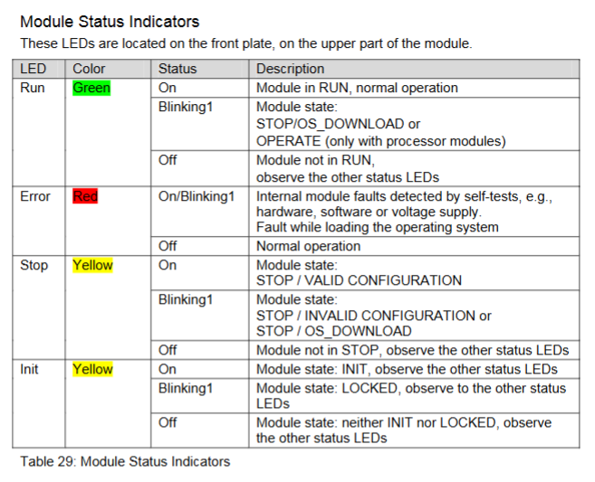
1. LED diagnostic indicator
(1) Indicator light grouping
Module status indicator lights (all modules): Run (green, running status), Error (red, fault), Stop (yellow, stop status), Init (yellow, initialization/lock status)
Redundancy indicator lights (processor/system bus module): Ess (yellow, module necessity indicator), Red (yellow, redundant operating status)
Fault indicator lights (processor module): System (system module fault), Field (I/O module field fault), Com (external communication fault)
(2) Definition of flicker frequency
Blinking1: Long on 600ms/Long off 600ms
Blinking2: Short on 200ms/Short off 200ms/Long on 600ms/Long off 600ms
Blinking-x: Ethernet communication synchronous flashing
2. Diagnostic history and online diagnosis
Diagnosis history: divided into short-term and long-term diagnosis. Short term diagnosis is a circular buffer, while long-term diagnosis stores user operations and configuration changes. Different modules have different storage capacities (such as X-CPU 01 supporting 2500 long-term events and 1500 short-term events)
Online diagnosis: viewed through the SILworX hardware editor online view, the faulty module is marked in red (severe fault) or yellow (minor fault), and supports viewing information such as module SRS, operating status, and consistency between configuration and actual module
3. Maintenance and Repair
Regular maintenance: Regular verification testing is required, and it is recommended to replace the fan regularly. Maintenance personnel must have professional qualifications and perform ESD protection
Fault handling: When the processor module fails, redundant modules take over control; When there is no redundancy, the controller shuts down, and the cause of the fault can be diagnosed through SILworX
Maintenance authorization: Only HIMA company has the authority to repair safety related systems and modules. Unauthorized intervention will result in the failure of safety functions and warranty
Lifecycle Management
1. Installation phase
Environmental requirements: working temperature 0-60 ℃, storage temperature -40-85 ℃, altitude<2000m, protection level IP20 (special scenarios require an IP54 or higher enclosure)
Wiring specifications: Supports 4 types of wiring schemes (single/redundant connector board+direct/FTAs connection), cables must be kept away from electromagnetic interference sources, and grounding must comply with SELV/PELV requirements
Heat dissipation considerations: A heat dissipation structure should be designed for a closed environment, and the effective heat dissipation area should be calculated based on the installation type to ensure that the operating temperature of the module does not exceed 60 ℃
2. Startup phase
(1) Control cabinet startup
Preprocessing: Test all input and output terminals for abnormal external voltage (such as 230V), check cable insulation resistance and grounding faults
Power supply inspection: Confirm that the polarity of the 24VDC power supply is correct, the voltage is stable, and the ripple meets the requirements
(2) PES startup
Startup steps: Set the system bus module IP and SRS → Specify the "responsible" system bus module → Configure the processor module → Interconnect the substrate → Log in to the system → Load the project → Start the system
Rack ID allocation: Modify through the system bus module to ensure that all modules on the substrate are in STOP state and the new ID configuration is consistent
3. Operation and shutdown
Operation monitoring: View system status, event records, and fault information through SILworX, and regularly backup project configurations
Shutdown disposal: Follow the requirements of the component manual for retirement and disposal to ensure electrical safety
Supplementary model
1、 Base Plates model
X-BASE PLATE 10 01 (10 slots, flat panel installation)
X-BASE PLATE 15 01 (15 slots, backplate installation)
X-BASE PLATE 15 02 (15 slots, 19 inch installation)
X-BASE PLATE 18 01 (18 slots, backplate installation)
2、 Module model
(1) Processor module
X-CPU 01
(2) System bus module
X-SB 01
(3) Communication module
X-COM 01
(4) I/O module
Analog input module
X-AI 32 01 (32 channels)
X-AI 32 02 SOE (32 channels, supporting event sequence recording)
Analog output module
X-AO 16 01 (16 channels)
Counter input module
X-CI 24 01 (24 channels)
Digital input module
X-DI 16 01 (16 channels)
X-DI 32 01 (32 channels)
X-DI 32 02 (32 channels, suitable for proximity switches)
X-DI 32 03 (32 channels)
X-DI 32 04 SOE (32 channels, supporting event sequence recording)
X-DI 32 05 SOE (32 channels, suitable for proximity switches, supports event sequence recording)
X-DI 64 01 (64 channels)
Digital output module
X-DO 12 01 (12 channels, relay output)
X-DO 12 02 (12 channels)
X-DO 24 01 (24 channels)
X-DO 24 02 (24 channels)
X-DO 32 01 (32 channels)
(5) Fan module
- OMRON
- ABB
- General Electric
- EMERSON
- Honeywell
- HIMA
- ALSTOM
- Rolls-Royce
- MOTOROLA
- Rockwell
- Siemens
- Woodward
- YOKOGAWA
- FOXBORO
- KOLLMORGEN
- MOOG
- KB
- YAMAHA
- BENDER
- TEKTRONIX
- Westinghouse
- AMAT
- AB
- XYCOM
- Yaskawa
- B&R
- Schneider
- KONGSBERG
- NI
- WATLOW
- ProSoft
- SEW
- ADVANCED
- Reliance
- TRICONEX
- METSO
- MAN
- Advantest
- STUDER
- DANAHER MOTION
- Bently
- Galil
- EATON
- MOLEX
- DEIF
- B&W
- ZYGO
- Aerotech
- DANFOSS
- Beijer
- Moxa
- Rexroth
- Johnson
- WAGO
- TOSHIBA
- BMCM
- SMC
- HITACHI
- HIRSCHMANN
- Application field
- XP POWER
- CTI
- TRICON
- STOBER
- Thinklogical
- Horner Automation
- Meggitt
- Fanuc
- Baldor
- SHINKAWA
- Other Brands
- UniOP
- KUKA
- Iba
- Beckhoff
-
 Basler XR2002F Voltage Regulator 9139400101
 -
 Basler 2D80367G23 DXCB De-Excitation Module 1200V 5000A
 -
 Basler SR4A-2B15B3A Static Regulator 120V 50/60Hz
 -
 Basler SSR 125-12NF Static Regulator 9 1859 00 106
 -
 Basler BE1-BPR Breaker Protection Relay 9272000315
 -
 Basler SSR 63-12 Static Regulator 9 1859 00 101
 -
 Basler AEM-2020 Analog Expansion Module
 -
 Basler BE 25231-001 Transformer BE25231001
 -
 Basler MVC 108 Manual Voltage Control 9037000102
 -
 Basler PSS-100-Y5 Power System Stabilizer 0.1-5.0Hz
 -
 Basler Electric BE1A-25-M1G-A6T-N4V1F Sync-Check Relay
 -
 Basler Electric SR8A2B10B1A Static Voltage Regulator
 -
Basler Electric SR8A2B10B1A Static Voltage Regulator
-
Basler Electric SSR 125-12 Static Voltage Regulator 9185900102
-
 Basler Electric 90-73900-102 Power Supply (Westinghouse 2374A07G03)
 -
 Basler Electric 9400200117 Control Power Unit 12/24VDC 20W
 -
Basler Electric BE1-87G Solid State Generator Differential Relay
-
 Basler Electric BE1-32R Style C3ED1TA0S1F Solid State Protective Relay
 -
Basler Electric SR32A2B05B3E Static Voltage Regulator
-
 Basler Electric SR8A2B06B3A Static Voltage Regulator
 -
Basler MOC3502 90-72300-116 Motor Potentiometer
-
 Basler SR4A2310B1A Static Voltage Regulator
 -
 Basler Electric 90-88800-102 PRS-250 Veri-Sync Relay
 -
Basler Electric 90-88800-102 PRS-250 Veri-Sync Relay
-
Basler SR4A-2B05A3E Static Regulator SR4A2B05A3E
-
 Basler 9-0723-00-130 9072300130 Control Module
 -
 Basler BE1-79MA10A6JC0L0F Reclosing Relay
 -
 Basler CBS-377 Current Boost System 91096001
 -
Basler SR4A1B05A3A Static Regulator 480V 62.5V 10VA
-
 Basler BE159N A7ED1JC0S0F Protective Relay BE159N-0
 -
 Basler BE3-25A Auto-Synchronizer S.No. 728
 -
 Basler BE1-50 Instantaneous Overcurrent Relay G4EA1RG0N0F
 -
 Basler Electric KT3B Voltage Regulator
 -
 Basler Electric ACA2500-14GCSYM GigE Camera
 -
 Basler Electric XR2002F Voltage Regulator
 -
 Basler Electric BE1-50 Instantaneous Overcurrent Relay F2EA1PA0N5F
 -
 Basler Electric CBS 212A Current Boost System
 -
Basler Electric BE147NE3FE1PC3N3F Negative Sequence Voltage Relay
-
 Basler Electric BE1-79MA10A6JC0L0F Automatic Reclosing Relay
 -
Basler Electric BE1-59N A6E E1C B0N1F Neutral Overvoltage Relay
-
 Basler Electric MVC 108 Manual Voltage Control
 -
 Basler Electric BE1-59-A4E-E1C-A0N0F Overvoltage Relay
 -
Basler BE1-57/27R Solid State Protective Relay
-
 Basler BE3-25AX Time Overcurrent Relay
 -
BASLER ELECTRIC BE1-24/A1EF1JC1N0F / BE124A1EF1JC1N0F Overvoltage Relay
-
Basler Electric Solid State Protective Relay BE1-32R Style B2ED1PB0N0F
-
Basler BE3-51-3E1E1 9320000110 24VDC Overcurrent Relay
-
 Basler UFOV 260A Underfrequency Overvoltage Module
 -
 Basler 50F4EA1PA0N0F Instantaneous Overcurrent Relay
 -
Basler BE1-50 Instantaneous Overcurrent Relay
-
 Basler BE1-32 Solid State Protective Relay
 -
Basler SCP 250-G-60 VAR Power Factor Controller
-
Basler BE1-59N A5EE1KC0N0F Ground Fault Relay
-
Basler BE1-79A Reclosing Relay
-
Basler BE1-32R E1EA1OA0N0F Reverse Power Relay
-
 Basler DCQA-103 DCQC104-1 CMX-7D Circuit Board
 -
 Basler SSR125-12 Static Regulator 918500102
 -
Basler 90 17709 112 Regulator Control Board
-
 Basler AVC63-4 AVC634 Voltage Regulator
 -
 Basler 9 1049 04 100 PC Board Control Module
 -
Basler SR4A-2B03B3A Static Voltage Regulator
-
 Basler SR8A-2B15B3A Static Voltage Regulator
 -
 Basler KR7FFX Static Regulator 840V
 -
 Basler EL200-7 Voltage Regulator 90-660VAC 7A
 -
 Basler PRP210-1 Reverse Power Relay 9056300102
 -
 Basler SSR 63-12 Static Regulator 600VAC
 -
 Basler 9289901106 Digital Board
 -
Basler DECS100 Voltage Regulator DECS100A01
-
Basler Electric CEM-2020 Contact Expansion Module
-
Basler Electric BE3-25-1 C1 N4 Synchronizing Check Relay
-
Basler Electric ACA2000-50GM GigE Camera 2MP 50fps
-
 Basler Electric ACA2240-20GMSYM GigE Camera Sony IMX264
 -
Basler BE1-50G Ground Overcurrent Relay
-
Basler PRS250 Veri-Sync Relay
-
Basler MOC2199 Output Module
-
 Basler UFOV 260A Underfrequency Overvoltage Module
 -
 Basler BE-15482-001 Control Module
 -
Basler LSP4-7 Protective Relay
-
 Basler SCP 250-G-60 VAR Power Factor Controller
 -
Basler BE146N Negative Sequence Overcurrent Relay
-
Basler APR63-5 Automatic Voltage Regulator
-
Basler 9507900107 SR8A Retrofit Voltage Regulator
-
Basler BE1-320 Directional Power Relay
-
 Basler KR7F Voltage Regulator 9116200100
 -
Basler UFOV 260A Overvoltage Protective Module
-
 Basler AEC63-7 Analog Excitation Controller
 -
Basler 9992D90G01 Control Module
-
Basler 6966D22G01 Control Board
-
Basler 6965D40G01 Control Board
-
 Basler BE1-50/51M-104 Overcurrent Relay
 -
Basler BE1-BPR Programmable Breaker Relay
-
 BASLER Electric SSR 125-9 1256 00 102 Static Voltage Regulator
 -
Basler Electric MVC 112 Manual Voltage Control
-
 Basler Electric 9321000102 Control Module
 -
 Basler Electric RA-70-MDCT7 Rectifier Assembly
 -
 Basler Electric ACA1300-60GM GigE Camera
 -
 Basler Electric 6427C85G01 Interface Board
 -
Basler Electric 6965D05G01 Control Board
-
Basler Electric ACA2500-14UC Current Transducer
-
Basler Electric 9170206111 Protective Relay
-
Basler Electric BE1-11-G6D1M1J1P0E000 Protection Relay
-
Basler Electric BE1-50/51B-107 Overcurrent Relay
-
 Basler 9121000106 Voltage Controller
 -
 Basler B3E-E1P-A0N0F Solid State Protective Relay
 -
 Basler 9121000106 Manual Voltage Control
 -
Basler PRP320 Motor Pull-out Relay
-
 Basler SSE-N 250-9KW Shunt Exciter Regulator
 -
 Basler BE1-50-51B-107 Overcurrent Relay
 -
 BASLER ELECTRIC MVC 108 MANUAL VOLTAGE CONTROL MODULE 9 0370 00 102
 -
Basler BE1-59N-A7E-D1J-D0N0F Ground Overvoltage Relay
-
Basler BE1-46N-G1E-B8P-B0N0F Negative Sequence Overcurrent Relay
-
Basler BE1-951 Overcurrent Protection System
-
 Basler Electric MOC2199 Motor Operated Potentiometer
 -
Basler Electric BE1-60 Voltage Balance Solid State Relay B1FA1C1M1F
-
Basler Electric BE1-67N Directional Overcurrent Relay
-
Basler Electric PIA2400-17GM Interface Module
-
 Basler Electric V6RAB Rectifier Module
 -
Basler Electric BE1-32R Reverse Power Relay B2E E1R A0N1F
-
Basler Electric IFM-150 Firing Circuit Chassis 120V AC
-
 Basler Electric IFM-102 Firing Circuit Chassis 120V AC
 -
 Basler Electric 9170206111 NSNP Control Module
 -
Basler Electric SSR 63-12 Static Voltage Regulator
-
 Basler UFOV 260A Overvoltage Protective Module
 -
Basler SCA1300-32GM CCD Camera Lens Enclosure
-
Basler BA1-27 Under Voltage Relay
-
Basler 149D866G06 Control Board
-
 Basler 9072300130 Power Supply Module
 -
Basler CBS 305 Current Boost System


