
YASKAWA MEMOCON-SC 2000 series reversible counter module
Reset logic: When the external reset or current value reset signal is ON, the count stops and clears to zero
(3) Ladder diagram configuration
Core parameters: Coincidence preset value=1000, count width=2000 (maximum value 999999 in GL20 6-digit mode)
Counting process: ADD count up to 1000 → Coincidence output ON → Continue counting up to 2000 → Auto reset → Repeat loop
3. Sampling Counter
(1) Core functions
Basic ability: When receiving external sampling signals, latch the current count value and store it in the designated input register
Storage allocation: Counter 1 data is stored in input registers 1-2; Counter 2 data is stored in input registers 3-4
Sampling control: The sampling frequency can be reset through the "output disable" signal
(2) Key parameters
Sampling period: T ≥ 10ms, and must meet T ≤ (2 ¹⁹ -1)/(f · k) (GL20) or T ≤ (2 Ω³ -1)/(f · k) (GL60S), where f is the input pulse frequency and k is the magnification ratio
Signal requirements: Sampling signal ON response time<1ms, OFF response time<2ms, pulse width ≥ 5ms
(3) Operational logic
Initial state: When switching to sampling counter mode, the current value and carry/borrow flag are reset to zero
Data update: When the current value is preset, the sampled value is synchronously updated to the preset value
4. Memory Counter
(1) Core functions
Basic ability: When triggered by external sampling signals, latch the current count value and store it in the built-in data memory in the order of reception (up to 999 sets of data can be stored)
Data reading: By specifying the address through the "pointer command", the corresponding stored data can be read from the input register
Coincidence output: When the amount of stored data reaches the preset value, output a coincidence ON signal
(2) Key parameters
Storage limit: Stop sampling after the storage capacity reaches 999; When the preset value is 0, no coincidence signal is output
Sampling period: As required by the sampling counter (T ≥ 10ms, meeting frequency related constraints)
Read latency: After the local I/O pointer command is turned on, the data read latency is ≤ 3 scan cycles; Remote I/O ≤ 5 scanning cycles
(3) Operational logic
Reset control: When the "output disable" signal is turned on, the stored data is reset to zero, the storage count is reset, and the coincidence output is turned off
Pointer feature: When the pointer command is OFF, the input register displays the current count value; Display data stored at the specified address when turned on
Internal interface and signal definition
1. I/O allocation (interaction between CPU and B2801)
Interface type allocation specification signal flow direction
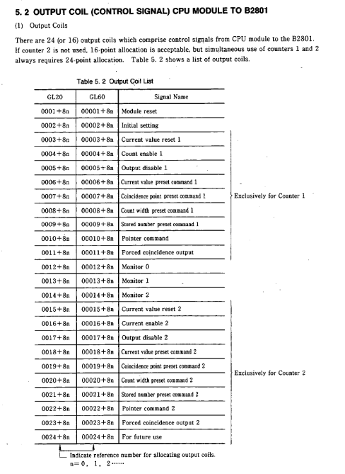
Output coil 24 points (dual counter)/16 points (single counter) CPU → B2801 (control signal)
Input relay 16 points (dual counter)/8 points (single counter) B2801 → CPU (status signal)
4 output registers (binary allocation) CPU → B2801 (set data)
4 input registers (binary allocation) B2801 → CPU (monitoring data)
2. Core control signal (output coil)
Signal Name Function Description Effective Methods
Module reset initializes internal RAM and external I/O signals, and the counter returns to its default value, triggering OFF → ON
Initial setting: Configure the counter function mode (compare/cycle/sample/store) OFF → ON trigger (count enable needs to be OFF)
Count enable, in conjunction with an external enable signal (ENB), allows the counter to count ON effectively
Output disable: Disable coincidence output or reset coincidence signal ON to be effective
The preset command (Current/Consensus/Count width preset) sets the current value, coincidence point, and count width OFF → ON trigger
Pointer command stores counter data, reads address specified ON is valid
3. Status feedback signal (input relay)
Signal Name Function Description Status Definition
READY module self diagnosis result (ROM/RAM/WDT check) ON=normal; OFF=abnormal
Preset ACK/NAK preset operation completion status feedback ACK=successful; NAK=Failed
Carry/Borrow count overflow feedback ON=1 scan cycle (compare/loop mode); Storage data overflow (sampling/storage mode)
Coincidence output - Coincidence signal output status feedback ON=coincidence condition satisfied
Scanning time error: CPU scanning time too short ON=error; OFF=Normal
4. Definition of Register Data
(1) Output register (set data)
1-2: Counter 1 dedicated (pulse mode, counting multiplier, coincidence mode, function selection, preset value, etc.)
3-4: Counter 2 dedicated (same as counter 1 configuration item)
Data range: GL20 (3-digit decimal); GL60S (4-digit decimal)
(2) Input register (monitoring data)
1-2: Counter 1 monitoring (current value, sampled value, stored data, etc.)
3-4: Monitoring of counter 2 (same as monitoring item of counter 1)
Monitoring mode: Switch through the combination of "Monitor 0~2" (e.g. 0-0-0=current value; 0-1-1=sampling times)
External interface and terminal connection
1. Front panel layout
LED indicator lights: RDY (self diagnostic status), 1ENB/2ENB (counting enabled), 1PHA/2PHA (phase A input), 1PHB/2PHB (phase B input), 1INC/2INC (addition counting), 1DEC/2DEC (subtraction counting), 1EQU/2EQU (coincidence output), 1ERR/2ERR (error alarm)
- OMRON
- ABB
- General Electric
- EMERSON
- Honeywell
- HIMA
- ALSTOM
- Rolls-Royce
- MOTOROLA
- Rockwell
- Siemens
- Woodward
- YOKOGAWA
- FOXBORO
- KOLLMORGEN
- MOOG
- KB
- YAMAHA
- BENDER
- TEKTRONIX
- Westinghouse
- AMAT
- AB
- XYCOM
- Yaskawa
- B&R
- Schneider
- KONGSBERG
- NI
- WATLOW
- ProSoft
- SEW
- ADVANCED
- Reliance
- TRICONEX
- METSO
- MAN
- Advantest
- STUDER
- DANAHER MOTION
- Bently
- Galil
- EATON
- MOLEX
- DEIF
- B&W
- ZYGO
- Aerotech
- DANFOSS
- Beijer
- Moxa
- Rexroth
- Johnson
- WAGO
- TOSHIBA
- BMCM
- SMC
- HITACHI
- HIRSCHMANN
- Application field
- XP POWER
- CTI
- TRICON
- STOBER
- Thinklogical
- Horner Automation
- Meggitt
- Fanuc
- Baldor
- SHINKAWA
- Other Brands
- UniOP
- KUKA
- Iba
- Beckhoff
-
 Basler D90 96801 100 PCB Card
 -
 Basler XR2002F Voltage Regulator (110 VAC, 48-480 Hz)
 -
 Basler SR8A-2B14B3A Regulator
 -
 Basler 9561500100 Module
 -
 Basler DECS-400 BE1-11 System
 -
 Basler DECS-100-B15 Excitation Control
 -
 Basler SCP 210 Frequency Controller
 -
 Basler SR4A-2B15B3A Static Voltage Regulator
 -
 Basler BE1-32R Power Relay
 -
 Basler PIA2400-17GM Power Interface Adapter
 -
 Basler MVC 232 Manual Voltage Control Module
 -
 Basler SSR 32-12 Static Voltage Regulator
 -
 Basler 5MW AVR Generator Voltage Regulator
 -
 Basler VR63-4B Voltage Regulator
 -
 Basler DECS-100-A05 AVR for Engine Generator
 -
 Basler DECS-100-B15 Automatic Voltage Regulator
 -
 Basler BE1-32R Directional Power Relay
 -
 Basler BE1-87B Differential Relay
 -
 Basler UFOV 260A Protective Module
 -
 Basler 9-2614-02-100 PCB Rev M
 -
Basler DECS-100-B15 Digital AVR
-
 Basler 9284900103 PS DECS-400N
 -
 Basler D4N3H1U Intertie Protection
 -
 Basler DECS-100-B15 A15 AVR
 -
 Basler KR4F Voltage Regulator
 -
 Basler BE26434 T14 Transformer
 -
 Basler SR8A-2B15B3A Regulator
 -
 Westinghouse 774B472A12 AR Relay
 -
Basler DECS-100-B15 AVR
-
Basler XR2002F Regulator 110V
-
Basler SR125-E Static Regulator
-
 Basler SSR 125-12 Regulator
 -
 Basler MOC2599 Motor Pot
 -
 Basler BE1-DFPR Feeder Relay
 -
 Basler CBS 305 Current Boost
 -
 Basler BE1-25 AutoSync
 -
 Basler MVC 300 Voltage Control
 -
 Basler BE3-25A AutoSync
 -
 Basler KR7FF Static Regulator
 -
 Basler 90-49000-100 Regulator
 -
 Basler 880 kVA Dry Type Transformer Specs
 -
 Basler Electric BE1-25 Sync-Check Relay Specs
 -
 Basler SSR 125-12 Voltage Regulator Specs
 -
 Basler Electric BE1-851 Overcurrent Relay Review
 -
Basler Electric 149D930G02 Control Sub-Assembly
-
 Basler Electric BE1-81O/UT Frequency Relay Specs
 -
 Basler Electric BE1-51/27C Overcurrent Relay
 -
 Basler Electric 149D956G02 Industrial Component
 -
Basler Electric BE1-51A Overcurrent Relay Specs
-
 Basler Electric BE1-40Q Loss of Excitation Relay
 -
 Basler DECS-200 Excitation Control System
 -
 Basler DECS-200 Voltage Regulator 56-277V AC / 125V DC
 -
Basler BE1-87T Transformer Differential Relay
-
 Basler RDP-110-S1 Protection Relay
 -
 Basler BE1-700V Digital Protective Relay
 -
 Basler BE1-951 Overcurrent Protection System
 -
 Basler DECS-300 Digital Excitation Control
 -
 Basler DECS-200 Digital Excitation Control
 -
 Basler DECS-200-1C Excitation Control System
 -
Basler DECS-200-1L Digital Excitation Control
-
 Basler Electric BE1-GPS Generator Protection System
 -
Basler Electric DECS-200-1C Digital Excitation Controller
-
 Basler Electric DECS125-15 Excitation Control with Power Module
 -
 Basler Electric BE1-87G Differential Relay
 -
 Basler Electric BE1-11 Protection System I5A3M2P2N0EA00
 -
Basler Electric DECS-200-1C Excitation Control System
-
Basler Electric BE1-11g Generator Protection Relay
-
Basler Electric DECS 125-15-B2C1 V2.0.9 Excitation Control
-
 Basler Electric BE1-81O/UT3ED1JA7N2F Frequency Relay
 -
Basler Electric BE1-81O/UT3EE1YB7N1F Frequency Relay
-
 Basler Electric DECS-200-1L Digital Excitation Control System
 -
Basler DECS125-15-B2C1 Excitation Control
-
 Basler 9507900205 SSR Retrofit Voltage Regulator
 -
 Basler BE2000E Digital Voltage Regulator
 -
 Basler BE1-GPS Generator Protection System
 -
Basler DECS-250-CN1CN1N Digital Excitation Control
-
 Basler DGC-2020 Genset Controller
 -
 Basler BE1-81O UT3ED1LA7N0F Frequency Relay (Variant)
 -
 Basler BE1-81O UT3EE1YA9S0F Frequency Relay (Variant)
 -
Basler BE1-81O Over/Under Frequency Relay
-
Basler DECS125-15 Digital Excitation Control
-
Basler Electric BE1-951 Overcurrent Protection System
-
 Basler Electric BE1-700V Digital Protective Relay
 -
 Basler Electric APR63-5 Automatic Voltage Regulator
 -
Basler Electric BE1-851 Overcurrent Protection System
-
Basler Electric DECS-250-LN1SN1N Excitation Control
-
 Basler Electric BE1-87T Transformer Differential Relay
 -
Basler Electric DECS-200-1L Excitation Control System
-
 Basler Electric 9310300100 DECS-300 Excitation Control
 -
 Basler Electric SSE-N 125-4.5KW Shunt Exciter Regulator
 -
 Basler Electric DGC-2020HD-5NS1DNSBA Genset Controller
 -
Basler Electric BE1-81-O/UT3EE1JB7N1F Frequency Relay
-
Basler Electric BE1-81T1EE1WA0N1F Frequency Relay
-
 Basler Electric BE1-25M1EA6PN5R1F Sync-Check Relay
 -
 Basler Electric BE1-GPS Generator Protection System
 -
Basler Electric DECS-250-LN1SN1N Excitation Control Rev V
-
 Basler Electric DECS-250-CN2CN1N Excitation Control
 -
Basler Electric BE1-50/51B-207 Overcurrent Relay
-
Basler Electric DECS-300-C0N0 Excitation Control System
-
Basler Electric DECS-200 Digital Excitation Control System
-
Basler Electric DECS-250-LN1CN1N Excitation Unit
-
Basler Electric DECS-250 LN2SA1D Excitation Unit Specs
-
Basler Electric BE1-87T Transformer Relay Review
-
Basler Electric BE1-11 Protection System
-
Basler Electric BE1-GPS100-E4N1H1N Protection System
-
 Allen-Bradley 442G-MABH-R Safety Module
 -
 Beckhoff CX1030-0111 PLC Assembly Profile
 -
 FANUC IC693CPU364 PLC Module
 -
 Orange Denmark Type 200816 220 PLC Specs
 -
 OMRON C200H-SNT31 Sysmac PLC Module
 -
 Allen Bradley 20AB022A3AYNANC0 PowerFlex 70
 -
 OMRON C200HW-PCU01 Position Control Unit
 -
 ABB AO845A-eA Analog Output Module
 -
 OMRON CJ1M-CPU22 CPU Unit
 -
 Allen Bradley 100-E265ED11 Contactor
 -
 Honeywell 51304511-100 Interface Module
 -
 SOLEXY BXF3S0101N0018 Gateway Module
 -
 OMRON CJ2H-CPU65 CPU Unit
 -
 Automation Direct GS2-45P0 AC Drive
 -
 M68-2000 2-Axis Motion CNC Controller
 -
 OMRON CJ1M-CPU11 V3.0 PLC CPU Unit
 -
 OMRON CJ1W-NC413 4-Axis Positioning Controller
 -
 OMRON 3G2A3-PRO16 Programming Console HMI
 -
 Siemens 3VT8440-2AA04-2GA2 Molded Case Circuit Breaker
 -
 Siemens 3RT5045 Contactor Series
 -
 OMRON C200HS-CPU01-E SYSMAC PLC Controller
 -
 OMRON C500-NC103-E Positioning Control Unit
 -
 OMRON CJ1W-TC001 Temperature Control Unit


