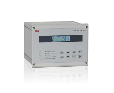
How to determine if the GE MLJ synchronous check relay is in calibration mode?
F5 frequency slip (Δ f) displays the frequency difference in mHz, and overflow is displayed when the voltage is less than 9V.
Record and store the VL, VB, Δ V, Δ θ, and Δ f values when the last closing condition is met for F6-F10.
The F11 test function display screen is fully lit and flashing, and the LED lights up simultaneously to verify the hardware's normal operation; When the digital input is activated, the corresponding LED flashes.
The F12 line/bus status is indicated by the upper and lower segments of the display screen: the upper segment is lit up to indicate "live", the lower segment is lit up to indicate "power-off", and the middle segment is lit up to indicate that the voltage is between the threshold values.
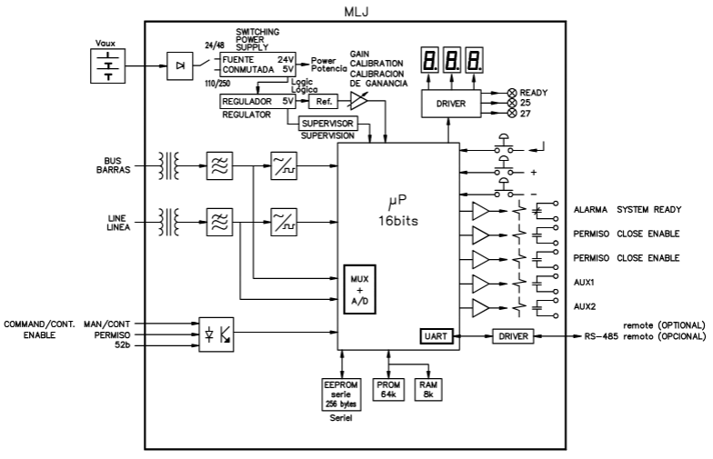
Set mode parameter configuration
After entering the setting mode, switch the setting items with the+/- keys, press ENTER to enter the modification, and press ENTER again to confirm after adjustment. The main settings are as follows:
1. Basic configuration (0-1, 6-1, 6-2)
0-1 frequency: Choose 50Hz or 60Hz (default 50Hz).
6-1 Communication Address: Set Modbus address (1-255, default 1).
6-2 baud rate: Select the communication rate (0.3-38.4kbaud, default 9.6kbaud).
2. Synchronize check parameters (1-1 to 2-2)
1-1 voltage difference (Δ V): 2-90V (step size 0.5V, default 15V).
1-2 phase angle difference (Δ θ): 2-60 ° (step size 1 °, default 10 °).
1-3 frequency slip (Δ f): 10-500MHz (step size 10mHz, default 20mHz).
1-4 continuous mode delay: 0.1-99.0s (step size 0.1s, default 0.1s).
- EMERSON
- Honeywell
- CTI
- Rolls-Royce
- General Electric
- Woodward
- Yaskawa
- xYCOM
- Motorola
- Siemens
- Rockwell
- ABB
- B&R
- HIMA
- Construction site
- electricity
- Automobile market
- PLC
- DCS
- Motor drivers
- VSD
- Implications
- cement
- CO2
- CEM
- methane
- Artificial intelligence
- Titanic
- Solar energy
- Hydrogen fuel cell
- Hydrogen and fuel cells
- Hydrogen and oxygen fuel cells
- tyre
- Chemical fiber
- dynamo
- corpuscle
- Pulp and paper
- printing
- fossil
- FANUC
- Food and beverage
- Life science
- Sewage treatment
- Personal care
- electricity
- boats
- infrastructure
- Automobile industry
- metallurgy
- Nuclear power generation
- Geothermal power generation
- Water and wastewater
- Infrastructure construction
- Mine hazard
- steel
- papermaking
- Natural gas industry
- Infrastructure construction
- Power and energy
- Rubber and plastic
- Renewable energy
- pharmacy
- mining
- Plastic industry
- Schneider
- Kongsberg
- NI
- Wind energy
- International petroleum
- International new energy network
- gas
- WATLOW
- ProSoft
- SEW
- wind
- ADVANCED
- Reliance
- YOKOGAWA
- TRICONEX
- FOXBORO
- METSO
- MAN
- Advantest
- ADVANCED
- ALSTOM
- Control Wave
- AB
- AMAT
- STUDER
- KONGSBERG
- MOTOROLA
- DANAHER MOTION
- Bently
- Galil
- EATON
- MOLEX
- Triconex
- DEIF
- B&W
- ZYGO
- Aerotech
- DANFOSS
- KOLLMORGEN
- Beijer
- Endress+Hauser
- MOOG
- KB
- Moxa
- Rexroth


Email:wang@kongjiangauto.com


