
How to install Hirschmann MS20/MS30 series industrial Ethernet switches?
How to install Hirschmann MS20/MS30 series industrial Ethernet switches?
Overview
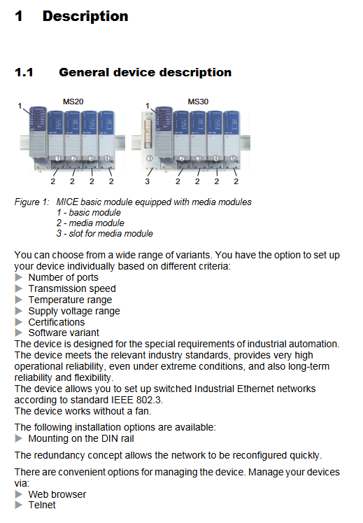
The installation user manual for Hirschmann MS20/MS30 series industrial Ethernet switches (Release 14 03/2023 version) covers four major modules: equipment overview, safety specifications, installation process, basic configuration, maintenance, and technical parameters. It provides detailed instructions on the hardware composition of the equipment (basic module, media module, SFP transceiver, etc.), installation steps (DIN rail installation, wiring, DIP switch configuration), safety compliance requirements (ATEX, IECEx and other hazardous environment certifications), and technical parameters (power supply range of 18-60V DC, working temperature -40 ℃~+70 ℃, port type supporting 10/100/1000Mbit/s twisted pair/fiber ports). It also offers a global technical support channel to provide comprehensive guidance for equipment deployment and operation in industrial scenarios.
Preparation before installation( ✅ Complete one and check one
Inspection item operation content verification standard remarks
1. Check the integrity of the packaging: basic module x 1, terminal block (4-pin x 2/6-pin x 1), label x 1, installation manual x 1. There are no missing or damaged items during transportation (such as shell deformation or port damage). If accessories are missing, contact the supplier for replacement
2. Equipment model matching confirmation: The product code is consistent with the requirements (key verification: number of ports, temperature range, power supply range). The 6th and 7th digits of the code are equal to the required number of ports (08/16/24); 10th position=temperature range (S/T/E); 11th position=Power supply range (A/C/E) Example: MS30-1602-T-C-H corresponds to 16 100Mbps+2 1G, -40~70 ℃, 18-60V DC
3. Installation environment confirmation: 1. Environmental temperature: meets the equipment temperature level (S: 0~60 ℃; T/E:-40~70℃); 2. Installation location: well ventilated, with a reserved space of ≥ 10cm above and below; 3. Hazardous environment: If it is an explosion-proof scenario, the equipment needs to be labeled with ATEX/IECEx. The environment should be free of condensation and strong electromagnetic interference; Dangerous environments must meet Class I Division 2/ATEX 2G requirements and avoid installation near heat sources (such as frequency converters) or areas with high dust
4. Essential tools and materials preparation: Phillips screwdriver, crimping pliers, wire stripping pliers; Materials: Cat5e and above twisted pair cables, fiber optic jumpers (matching port types), copper wires (≥ 1.5mm ²), and cable tie wires that meet specifications (75 ℃ copper wires); The type of fiber optic jumper is the same as SFP (such as LC single-mode jumper with SM SFP). Explosion proof tools are required for hazardous environments
5. Power supply preparation: Confirm that the power supply meets the requirements: 1 Voltage range (A: 18-32V DC; C/E: 18-60V DC); 2. Redundant power supply requires 2 independent power sources; 3. Class 2 power supplies with overcurrent protection (compliant with equipment fuse specification: 5A) are required in North America. DC power supplies need to distinguish between positive and negative poles, while AC power supplies need to be isolated and grounded
Hardware installation process (operated in sequence)
(1) Installation of media module/SFP transceiver
Common errors in step operation content verification standards
1. Remove the protective cap of the media module/SFP. The protective cap should not be damaged, and the port should be free of dust/metal debris. It is forbidden to touch the end face of the fiber optic port with hands
Align the basic module slot and insert the media module. Tighten the four corner screws to fully secure the module buckle. If the screws are not loose, install the module in the order of "left to right" to avoid slot misalignment
3 SFP transceivers are inserted into the gigabit slot, and the locking buckle makes a "click" sound when closed, making it difficult to easily remove. Only Hirschmann original SFP is used (third-party SFP may not be compatible)
(2) DIN rail installation
Step operation content verification standard safety precautions
1. Slide the top buckle of the device to a 35mm DIN rail (compliant with DIN EN 60715) and ensure that the buckle fully fits the rail without any looseness. The rail should be securely fixed to prevent the device from shaking
Press the bottom lock of the device and confirm that the device is fixed. Pull the device firmly without displacement. During installation, avoid squeezing the port and terminal block
(3) Grounding operation
Key requirements for step operation content verification standards
1. Choose grounding method: ① DIN rail grounding (priority); ② Special grounding screw grounding resistance ≤ 4 Ω. In hazardous environments, dual grounding (rail+screw) is required
If using screws for grounding, connect the grounding wire (with the same specifications as the power supply wire) and ensure that the grounding wire is not loose and in good contact with the shell. The grounding wire should not be laid in the same bundle as the power wire
- OMRON
- ABB
- General Electric
- EMERSON
- Honeywell
- HIMA
- ALSTOM
- Rolls-Royce
- MOTOROLA
- Rockwell
- Siemens
- Woodward
- YOKOGAWA
- FOXBORO
- KOLLMORGEN
- MOOG
- KB
- YAMAHA
- BENDER
- TEKTRONIX
- Westinghouse
- AMAT
- AB
- XYCOM
- Yaskawa
- B&R
- Schneider
- KONGSBERG
- NI
- WATLOW
- ProSoft
- SEW
- ADVANCED
- Reliance
- TRICONEX
- METSO
- MAN
- Advantest
- STUDER
- DANAHER MOTION
- Bently
- Galil
- EATON
- MOLEX
- DEIF
- B&W
- ZYGO
- Aerotech
- DANFOSS
- Beijer
- Moxa
- Rexroth
- Johnson
- WAGO
- TOSHIBA
- BMCM
- SMC
- HITACHI
- HIRSCHMANN
- Application field
- XP POWER
- CTI
- TRICON
- STOBER
- Thinklogical
- Horner Automation
- Meggitt
- Fanuc
- Baldor
- SHINKAWA
- Other Brands
- UniOP
- KUKA
- Iba
- Beckhoff
-
 Basler DECS-200-2L Digital Excitation Control
 -
 Basler BE1-47N Voltage Phase Sequence Relay
 -
 Basler AEC63-7 Analog Excitation Controller 220-277V
 -
 Basler BE1-50/51B-107 Overcurrent Relay
 -
 Basler Electric BE1‑32R BE1‑E1P‑BON0F Protective Relay
 -
 Basler BE1-25 Solid State Time Overcurrent Relay M1EA6PA5S1F
 -
 Basler MVC 232 Manual Voltage Control Module 90 37000 103 60VAC 55VDC
 -
 Basler RAL6144-16GM Racer GigE Line Scan Camera
 -
 Basler SSR 63-12 Static Voltage Regulator
 -
 Basler BE1-51A Overcurrent Relay
 -
 Basler BE1-87T Solid State Protective Relay
 -
 Basler SR4A2B01B3A Static Voltage Regulator
 -
 Basler SSR 32-12 Static Voltage Regulator
 -
 Basler TRR00696 Transformer 1KVA 115V
 -
 Basler DECS-100-B15 AVR Replacement
 -
Basler BE1-27 Under-Voltage Relay
-
 Basler ACA2000-50GM Interface Module
 -
 Basler AEC63-7 Analog Excitation Controller
 -
 Basler PRS 250 Veri-Sync Relay
 -
 Basler SR4A-2B15B3A Static Voltage Regulator
 -
Basler BE1-32R Power Relay
-
Basler SR8A-2B06B3E Static Voltage Regulator
-
Basler BE1-81 O/U Frequency Relay
-
 Basler BE1-51A-K2E-W6M-B1N0F Overcurrent Relay
 -
Basler BE1-851 Overcurrent Relay G3A1S1 – 48-125V AC/DC
-
 Basler BEI-51 Overcurrent Relay – NSN 5945-01-293-2363
 -
Basler Electric L301KC Protective Relay – L301KC
-
 Basler DECS-100-B15 Automatic Voltage Regulator – Generator AVR
 -
 Basler SR4A-2B15B3A Static Voltage Regulator – SR4A2B15B3A
 -
 Basler UF 312 Under Frequency Protective Module – 9094700100
 -
Basler Electric MVC 232 Manual Control Module – 60VAC 55VDC 20A
-
Basler PRS 250 Veri-Sync Relay – Generator Synchronizing Relay
-
 Basler DECS-100-A05 Digital Regulator Review
 -
 Basler AEM-2020 Analog Expansion Module Specs
 -
 Basler DECS-100-B15 Digital Excitation Specs
 -
Basler Electric 9125600106 Regulator Component
-
Basler BE1-51A-K1E-W6M-B1N0F Overcurrent Relay
-
 Basler MVC-301 MVC 300 Excitation Controller
 -
 Basler SSR 32-12 Static Voltage Regulator
 -
 Basler 9-2849-00-101 Control Module
 -
Basler BE1-51A Overcurrent Relay
-
 Basler BE1-51/27R Overcurrent Relay
 -
 Basler BE1-51 Overcurrent Relay
 -
 Basler SR8A-2B15B3A Static Voltage Regulator
 -
 Basler BE32965001 Transformer and Timer Board
 -
 Basler 9174700100 EL200-7 Excitation Limiter
 -
 Basler BE2000E AVR Voltage Regulator
 -
Basler BE1-87G Differential Relay
-
 Basler BE21834001 Generator Control Module
 -
Basler DECS-100-B15 AVR
-
 Basler D90 96801 100 PCB Card
 -
 Basler XR2002F Voltage Regulator (110 VAC, 48-480 Hz)
 -
 Basler SR8A-2B14B3A Regulator
 -
 Basler 9561500100 Module
 -
 Basler DECS-400 BE1-11 System
 -
 Basler DECS-100-B15 Excitation Control
 -
 Basler SCP 210 Frequency Controller
 -
Basler SR4A-2B15B3A Static Voltage Regulator
-
Basler BE1-32R Power Relay
-
 Basler PIA2400-17GM Power Interface Adapter
 -
 Basler MVC 232 Manual Voltage Control Module
 -
 Basler SSR 32-12 Static Voltage Regulator
 -
Basler 5MW AVR Generator Voltage Regulator
-
 Basler VR63-4B Voltage Regulator
 -
Basler DECS-100-A05 AVR for Engine Generator
-
Basler DECS-100-B15 Automatic Voltage Regulator
-
Basler BE1-32R Directional Power Relay
-
Basler BE1-87B Differential Relay
-
 Basler UFOV 260A Protective Module
 -
 Basler 9-2614-02-100 PCB Rev M
 -
Basler DECS-100-B15 Digital AVR
-
 Basler 9284900103 PS DECS-400N
 -
 Basler D4N3H1U Intertie Protection
 -
 Basler DECS-100-B15 A15 AVR
 -
 Basler KR4F Voltage Regulator
 -
 Basler BE26434 T14 Transformer
 -
 Basler SR8A-2B15B3A Regulator
 -
 Westinghouse 774B472A12 AR Relay
 -
Basler DECS-100-B15 AVR
-
Basler XR2002F Regulator 110V
-
Basler SR125-E Static Regulator
-
Basler SSR 125-12 Regulator
-
Basler MOC2599 Motor Pot
-
 Basler BE1-DFPR Feeder Relay
 -
 Basler CBS 305 Current Boost
 -
Basler BE1-25 AutoSync
-
Basler MVC 300 Voltage Control
-
 Basler BE3-25A AutoSync
 -
 Basler KR7FF Static Regulator
 -
Basler 90-49000-100 Regulator
-
 Basler 880 kVA Dry Type Transformer Specs
 -
Basler Electric BE1-25 Sync-Check Relay Specs
-
 Basler SSR 125-12 Voltage Regulator Specs
 -
 Basler Electric BE1-851 Overcurrent Relay Review
 -
Basler Electric 149D930G02 Control Sub-Assembly
-
 Basler Electric BE1-81O/UT Frequency Relay Specs
 -
 Basler Electric BE1-51/27C Overcurrent Relay
 -
 Basler Electric 149D956G02 Industrial Component
 -
Basler Electric BE1-51A Overcurrent Relay Specs
-
 Basler Electric BE1-40Q Loss of Excitation Relay
 -
Basler DECS-200 Excitation Control System
-
 Basler DECS-200 Voltage Regulator 56-277V AC / 125V DC
 -
Basler BE1-87T Transformer Differential Relay
-
 Basler RDP-110-S1 Protection Relay
 -
 Basler BE1-700V Digital Protective Relay
 -
 Basler BE1-951 Overcurrent Protection System
 -
 Basler DECS-300 Digital Excitation Control
 -
 Basler DECS-200 Digital Excitation Control
 -
 Basler DECS-200-1C Excitation Control System
 -
Basler DECS-200-1L Digital Excitation Control
-
 Basler Electric BE1-GPS Generator Protection System
 -
Basler Electric DECS-200-1C Digital Excitation Controller
-
 Basler Electric DECS125-15 Excitation Control with Power Module
 -
Basler Electric BE1-87G Differential Relay
-
 Basler Electric BE1-11 Protection System I5A3M2P2N0EA00
 -
Basler Electric DECS-200-1C Excitation Control System
-
Basler Electric BE1-11g Generator Protection Relay
-
Basler Electric DECS 125-15-B2C1 V2.0.9 Excitation Control
-
Basler Electric BE1-81O/UT3ED1JA7N2F Frequency Relay
-
Basler Electric BE1-81O/UT3EE1YB7N1F Frequency Relay
-
 Basler Electric DECS-200-1L Digital Excitation Control System
 -
Basler DECS125-15-B2C1 Excitation Control
-
 Basler 9507900205 SSR Retrofit Voltage Regulator
 -
 Basler BE2000E Digital Voltage Regulator
 -
 Basler BE1-GPS Generator Protection System
 -
Basler DECS-250-CN1CN1N Digital Excitation Control
-
 Basler DGC-2020 Genset Controller
 -
Basler BE1-81O UT3ED1LA7N0F Frequency Relay (Variant)


